I have a gainclone that I built following the model on the Decibel Dungeon pages (a modified version of a design proposed by Thorsten Loetch). It has been running for about half a year now, and I just put it into a more refined case. It is my first attempt at DIY amps and have learned a bit, although my lack of electronic knowledge is still apparent. Nonetheless, my first attempt has been a success and am very happy with the results. I did notice a couple of things in doing this switch that I'm curious about and would like resolved.
1. I have a 20-0-20 transformer for each chip. The "20" connections go to the bridge rectifier. The GC schematics have no indication (as far as I know) of where the "0v" (ground?) connects into the circuit, if at all. I had it connected to the power star ground and everything worked fine. Upon switching cases, I thought that perhaps "0v" was not necessary to be connected to the circuit, but the amp sounded like crap and faded to nothing in a couple of seconds. I reconnected it to PSG and it worked again. I moved the "0v" connection in the circuit to the ground directly at the AC power inlet, and can tell no difference in sound. Where should the "0v" connection from the transformer go?
2. When the transformer is connected to the bridge rectifier but not the chip, I get roughly +-20v at the rails, but when I have the chip attached and the "0v" connection on the transformer connected to the circuit as mentioned above, I get +-27v at the rails. disconnect the "0v" and leave the chip circuit attached, and the voltage drops back to +-20, but of course, the amp doesn't work. What do I make of this?
thanks,
tim schaefer
Attachments
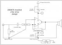
1) The 0 wire must connect to PSG for the gainclone to work. Please examine the transformer/bridge in the diagram at this link:
http://www.diyaudio.com/forums/showthread.php?s=&threadid=23592&highlight=
This wire (the 0) is the "power" ground and can (sometimes) effect the sound output if it is connected incorrectly.
There is good info here:
http://www.decdun.fsnet.co.uk/gaincloneFAQ.html
look under "How do I wire up the transformer".
2) You are measuring "pulsating" DC voltage out of the Bridge Rectifier. When you connect it to the GC the large filter capacitors attached smoth (filter) the pulses and the DC voltage is higher.
- Status
- Not open for further replies.