I believe in a very low impedance power supply, with the best ESR as possible.
But not only that, it can double as a low pass filter for mains-borne noise.
I've seen big fills in many commercial amplifiers
But the spirit of DIY is to improve on what's commercially available. 🙂
Dear,
I believe in a very low impedance power supply, with the best ESR as possible.
I've seen big fills in many commercial amplifiers, including Nelson Pass, and it seems to work very well in practice in an power amplifier.
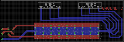
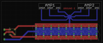
I still can't decide between option E or option C.
With kind regards
Bas
Can I ask a silly question? Why can't the capacitor bank be re-arranged so that the amps are on either side?
-Scott
Can I ask a silly question? Why can't the capacitor bank be re-arranged so that the amps are on either side?
-Scott
Dear Scott,
That isn't a silly question, and as a matter of fact, the amps are (multiple output transistors) on both sides as bridged amp. But for illustration I kept it simple.
With kind regards,
Bas
It may be easier to think of this problem in terms of the ORDER of the ground returns rather than a 'star' connection, like this:-
1. Closest to the transformer CT are the PSU cap ground returns
2. 1 cm away from that point is the speaker ground return
3. 1 cm away from that is the Zobel network return
3. 1 cm away from that is the PSU decoupling capacitors for the main supply rails and output devices - these are usually located on the amplifer PCB
4. 1cm awayfrom that are the front end decouping cap returns
5. 1cm away from that, the input ground connection.
I use 1 cm just to illustrate that they are separated - 5mm is also good enough.
Critically, make sure there are no opportujnities for magnetic coupling between the grounds - e.g. you would not run your main PSU cap return line next to you input ground line.
When I was (much) younger, I built quite a few amps (anyone remember the Elektor 'Equa' amp from about '77 or 76?) and a few others. They all hummed like crazy, but I learned about grounding when I ended up doing very small signal instrumentation design work. Once you get the hang of it, you can get some amazing results.
Check out Doug Self's advice on grounding in his book.
It may be easier to think of this problem in terms of the ORDER of the ground returns rather than a 'star' connection, like this:-
1. Closest to the transformer CT are the PSU cap ground returns
2. 1 cm away from that point is the speaker ground return
3. 1 cm away from that is the Zobel network return
3. 1 cm away from that is the PSU decoupling capacitors for the main supply rails and output devices - these are usually located on the amplifer PCB
4. 1cm awayfrom that are the front end decouping cap returns
5. 1cm away from that, the input ground connection.
I use 1 cm just to illustrate that they are separated - 5mm is also good enough.
Critically, make sure there are no opportujnities for magnetic coupling between the grounds - e.g. you would not run your main PSU cap return line next to you input ground line.
When I was (much) younger, I built quite a few amps (anyone remember the Elektor 'Equa' amp from about '77 or 76?) and a few others. They all hummed like crazy, but I learned about grounding when I ended up doing very small signal instrumentation design work. Once you get the hang of it, you can get some amazing results.
Check out Doug Self's advice on grounding in his book.
Dear Bonsai,
Thanks for your contribution. Sounds all logic to me. But Mr. Self does state in his book that the Zobel, LS return must come together at the same star-point.
With kind regards,
Bas
Thanks all for the help. It get more clear which direction to go. To be clear, I never had hum or groundloops in the PCB's I designed so far, but I just want to get the "best" out of it.
A few questions still remain. Can someone explain the principe behind rotel's grounding? (all grounds connected between a big copper plane between the reservoir capacitors.
I add two more illustrations to continue on your advice. I have now 4 options left to choose from. Please contribute 😀
With kind regards,
Bas
Attachments
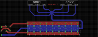
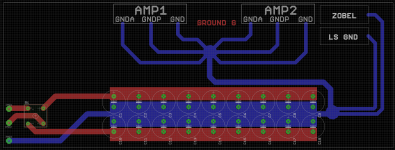
Okay, I just decide, I go with option C. The reason I choose this are the following reasons.
1: By routing the grounds to the right side, the capacitors can get placed closer to the amplifiers.
2: It is the most symmetrical way.
3: It keeps the star-point as far as possible away from the bridge-rectifier.
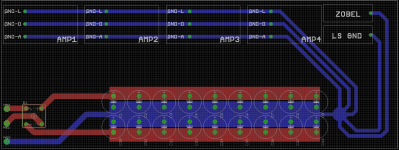
So I give a final example. Please feel free to comment. I can try to connect the Zobel and the LS GND to the transformer 0 volt line as suggested.
GND-L =Ground line level
GND-A = Ground amplifier heavy current
GND-D= Ground de-couple capacitors
It would be impossible to add a wire separately to each ground, so basicly the 4 modules are daisy-chained.
With kind regards,
Bas
1: By routing the grounds to the right side, the capacitors can get placed closer to the amplifiers.
2: It is the most symmetrical way.
3: It keeps the star-point as far as possible away from the bridge-rectifier.
So I give a final example. Please feel free to comment. I can try to connect the Zobel and the LS GND to the transformer 0 volt line as suggested.
GND-L =Ground line level
GND-A = Ground amplifier heavy current
GND-D= Ground de-couple capacitors
It would be impossible to add a wire separately to each ground, so basicly the 4 modules are daisy-chained.
With kind regards,
Bas
Attachments
Last edited:
Okay, I just decide, I go with option C. The reason I choose this are the following reasons.
1: By routing the grounds to the right side, the capacitors can get placed closer to the amplifiers.
2: It is the most symmetrical way.
3: It keeps the star-point as far as possible away from the bridge-rectifier.
So I give a final example. Please feel free to comment. I can try to connect the Zobel and the LS GND to the transformer 0 volt line as suggested.
GND-L =Ground line level
GND-A = Ground amplifier heavy current
GND-D= Ground de-couple capacitors
It would be impossible to add a wire separately to each ground, so basicly the 4 modules are daisy-chained.
With kind regards,
Bas
You should be fine with C, it's what I've always used with good experience. I don't like the newest version as much since the amplifiers will see different "reference" voltages along the daisy chain.
Scott
You should be fine with C, it's what I've always used with good experience. I don't like the newest version as much since the amplifiers will see different "reference" voltages along the daisy chain.
Scott
Dear Scott,
Point taken, but there are in total 6 amplifier modules. It is almost impossible to track separate ground tracks to each module ground. This would mean 4x6=24 ground tracks to the star point. Is daisy chaining really that bad?
I understand there will be a voltage difference between the first and the last amp module due the daisy-chaning ground track length. But if you feed separate lines, they will differ in length as well, don't you get the same reference difference then?
With kind regards,
Bas
Last edited:
A few questions still remain. Can someone explain the principe behind rotel's grounding? (all grounds connected between a big copper plane between the reservoir capacitors.
With kind regards,
Bas
It was probably forced by the reality of their physical layout. You also have to look at the conductors for that copper plane, is that a PCB with 4 oz. copper, a 1/8" thick sheet of copper plate, or a PCB with 1oz copper (doubtful). Remember that the noise induced on the ground is proportional to the current flowing times the total impedance of the path, resistance plus inductance. Nice, thick, heavy traces have lower resistance and inductance and the reduction of distortion performance was acceptable to them.
Scott
Dear Scott,
That is the problem is I have to route a ground line from the star to each individual capacitor and device separately instead of chaining. If I have to route so many tracks, they can't be thick, and increase the resistance per track 🙁
With kind regards,
Bas
Dear Scott,
Point taken, but there are in total 6 amplifier modules. It is almost impossible to track separate ground tracks to each module ground. This would mean 4x6=24 ground tracks to the star point. Is daisy chaining really that bad?
I understand there will be a voltage difference between the first and the last amp module due the daisy-chaning ground track length. But if you feed separate lines, they will differ in length as well, don't you get the same reference difference then?
With kind regards,
Bas
With a daisy chain one amplifier modulates the reference voltage of another amplifier with an unrelated signal. When the return paths are different lengths between each amplifier you will have slightly different return impdeance but one amplifier won't modulate the reference of the others...make sense?
In your drawing can't Amp3 and 4 be on the other side of the caps? Are all the amp boards on the same PCB as the power supply? Can you make separate amp boards so that you can discrete cable over?
-S
Dear Scott,
I need to keep it all on one PCB. Well I will follow your advice then, and find a way to ground each part separately. But it would't harm for example to join two de-couple capacitors per amp module and route them through one and the same track?
EDIT: Sorry I forgot to answer your question. AMP 3 and 4 can be on the other side of the board 😉
With kind regards,
Bas
I'm not sure I understand what you're saying about the de-couple capacitors, sorry my bad in interpretation.
Scott
I'm not sure I understand what you're saying about the de-couple capacitors, sorry my bad in interpretation.
Scott
Sorry. My bad. I mean the small 100nF capacitors close to the supply rails of each amp module.
With kind regards,
Bas
one more note,
Audio ground sin't really an issue, since all signal is balanced and floating from ground. Only the DC servo's need a ground reference.
With kind regards,
Bas
Audio ground sin't really an issue, since all signal is balanced and floating from ground. Only the DC servo's need a ground reference.
With kind regards,
Bas
Better than daisy chaining, a medium way could be auxiliaries star grounds.
One for the inputs, one route to main star ground
One for decouplings, one route to main star
And so on...
One for the inputs, one route to main star ground
One for decouplings, one route to main star
And so on...
Better than daisy chaining, a medium way could be auxiliaries star grounds.
One for the inputs, one route to main star ground
One for decouplings, one route to main star
And so on...
But would it harm to connect two de-coupling capacitors into one track?
With kind regards,
Bas
As long as they are decoupling caps from the same amp pcb i don't see a problem 😉
Must admit i like the ingenuity of bobodioulasso, seperate stars for different bits - but only if you are forced into that situation wiring wise, due to density of conductors 🙂
Must admit i like the ingenuity of bobodioulasso, seperate stars for different bits - but only if you are forced into that situation wiring wise, due to density of conductors 🙂
Hi Mark,
Sober again... no good. We must cheers again tonight since it is weekend! 😀
I will try first point to point grounding. I just peak into a schematic of a Cambridge Azur amp, where the designer (Mr. Self?) manage it to ground each point to the star all over the amplifier. So in basic it isn't impossible, but it means I have to do most of the PCB all over again. 😀 That said, this is the way to learn it so I should put my laziness aside.
I saw that Jeff Rowland use ground-planes in his amplifiers. Now I understand why.... 😀
With kind regards,
Bas
- Status
- Not open for further replies.
- Home
- Amplifiers
- Solid State
- Grounding options with multiple cap's