Hello
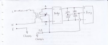
I have built an amplifier with the power arrangement as shown in the diagram attached. (I have used the same arrangement in previous built without problem.)
However, after minutes of running, the 10 ohm resistor smokes and blown. I then remove the 10 ohm resistor and made the following volatge measurement :
V between A and chassis : 62V ac
V between B and chassis : 45V ac (so blew the 10 ohm resistor)
V between C and chassis : 28V ac
V between E and chassis : 0.3V ac (I think this is normal)
(no observable dc voltages measured for above points)
I make the same measurement for my previous successful amp and all are within 0.1 V ac.
The Amp runs well after removing the 10 ohm. No hum and no hiss.
Can anyone suggest me what I have done wrong. Thx.
Attachments
Hi,
Can you read the voltage between A and the capacitors common ground. Same reading between B and the capacitors common ground. Post the reading.
Can you read the voltage between A and the capacitors common ground. Same reading between B and the capacitors common ground. Post the reading.
Shouldn't the voltage between point A and the chassis, and point C and the chassis, be the same (assuming point B is the center tap)?
Volatge between A and B : 18V ac
Volatge between B and C : 18V ac
These two measurement seems normal which is consistent with the manufacturer's spec.
DC output : 25V dc
This measurement should also be normal.
Volatge between B and C : 18V ac
These two measurement seems normal which is consistent with the manufacturer's spec.
DC output : 25V dc
This measurement should also be normal.
No to post1 layout.
The secondary wiring MUST go directly to the rectifier and then directly to the first stage smoothing capacitors.
All the wiring, primary and secondary, must be twisted into flow and return sets.
The extra centre tap wire must be twisted with the two ~~ secondaries and pass through the rectifier region unbroken and then twisted with the outgoing + & - to the caps.
The loop areas of these AC wires MUST be MINIMISED !!!!!!!!!
No to post1 layout.
The secondary wiring MUST go directly to the rectifier and then directly to the first stage smoothing capacitors.
All the wiring, primary and secondary, must be twisted into flow and return sets.
The extra centre tap wire must be twisted with the two ~~ secondaries and pass through the rectifier region unbroken and then twisted with the outgoing + & - to the caps.
The loop areas of these AC wires MUST be MINIMISED !!!!!!!!!
Sir AndrewT, Pls. draw the diagram so that easier for me to understand. TIA
+1 on the post by AndrewT.
He is describing the physical layout of the wiring - saying that certain wires need to be twisted tightly together where appropriate. These include the mains AC live+neutral going into the transformer, the transformer secondary and center tap wires, and the center tap (continuing on) with the +/- output of the rectifier. This last triple stays together until it reaches the capacitors. Connect all the grounds from the capacitor bank to one place using separate wires, and the center tap wire from the transformer connects there as well the ground wire coming from the case. in addition to a 10R ground loop breaking resistor you should include very high capacity diodes or (better) a bridge rectifier wired in a special way (look it up: ground loop breaker). This will improve safety.
Also, I have seen AndrewT talk about locating the main audio ground (MAG) "off of" the ground point for the capacitors. By "off of" I think he means connected by a wire, but I never got clarification from him on this. Maybe Andrew you can comment here?
I believe that the main purpose of the Main Audio Ground (MAG) is to provide a Good Reference for ALL the AUDIO circuits that need it.
To me that requires the MAG to be located close to ALL the Audio Circuits.
If we list those audio circuits we have:
Signal
Speaker
Amplifier
In a monoblock we can usually arrange for all those to be quite close to each other and my earlier contention is that the MAG should be physically located in amongst those audio circuits.
In a multiple channel amplifier, including dual mono, it is more difficult to get two signal and two amplifier and two speaker circuits very close together, but we must try our best. Again the MAG should be physically in the middle of that group.
Once that physical layout has been established then the builder con concentrate on HOW to arrange all the cable pairs (Flow and Return) to pass through the MAG. This is where the PSU finally enters the layout.
Last you can connect the MAG to Chassis.
The [transformer + rectifier + smoothing] MUST be kept in a tight low loop area group. One cannot fit that into the Audio Circuits Group. It is physically impossible.
The MAG can never perform if it is located ON the PSU smoothing capacitor link.
Always bring the PSU Zero Volts to the MAG. This PSU Zero Wolts wire is part of the twisted triplet that passes through the MAG in the journey from the PSU to the Amplifier.
Charlie,
I may have missed your request for clarification on that previous occasion, but I have described this MAG location very many times.
First is Safety.
Second is Audio.
The two requirements are very different.
Don't compromise one for the other.
Get BOTH right.
I drew a diagram with the intention of photographing it.......... draw the diagram so that easier for me to understand. ......
But got sidetracked.
And do not call me Sir.
I am not entitled to that !
I am plain Mr.
or, if you want to be techy, then Eur Ing.
I believe that the main purpose of the Main Audio Ground (MAG) is to provide a Good Reference for ALL the AUDIO circuits that need it.
To me that requires the MAG to be located close to ALL the Audio Circuits.
If we list those audio circuits we have:
Signal
Speaker
Amplifier
In a monoblock we can usually arrange for all those to be quite close to each other and my earlier contention is that the MAG should be physically located in amongst those audio circuits.
In a multiple channel amplifier, including dual mono, it is more difficult to get two signal and two amplifier and two speaker circuits very close together, but we must try our best. Again the MAG should be physically in the middle of that group.
Once that physical layout has been established then the builder con concentrate on HOW to arrange all the cable pairs (Flow and Return) to pass through the MAG. This is where the PSU finally enters the layout.
Last you can connect the MAG to Chassis.
The [transformer + rectifier + smoothing] MUST be kept in a tight low loop area group. One cannot fit that into the Audio Circuits Group. It is physically impossible.
The MAG can never perform if it is located ON the PSU smoothing capacitor link.
Always bring the PSU Zero Volts to the MAG. This PSU Zero Wolts wire is part of the twisted triplet that passes through the MAG in the journey from the PSU to the Amplifier.
Charlie,
I may have missed your request for clarification on that previous occasion, but I have described this MAG location very many times.
First is Safety.
Second is Audio.
The two requirements are very different.
Don't compromise one for the other.
Get BOTH right.
I still need to work out the MAG in my head. I have had issues with hum and noise pickup in the past, so this is something that I would very much like to get clarified down to the last dirty detail. First, let me present a figure that I think might well illustrate the physical wiring layout (this is from a post on this forum):
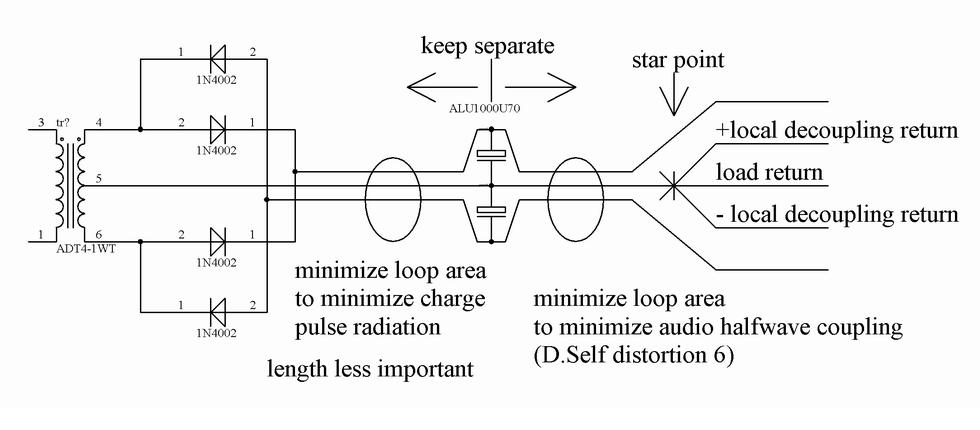
This shows the wires that should be tightly twisted. It could be a little clearer about this from the transformer secondary to the bridge rectifier - there will often be a length of wire here that needs to be twisted. Also, what is not shown is where to connect the chassis/earth connection. What IS shown I think is a MAG star point that is removed from the ground point between the caps.
Now on to questions, etc.:
I often build chip amps into wooden loudspeaker cabinets, in which case there is not metal enclosure around anything. I connect the earth to the point between the capacitors. Is this OK or might there be a better way?
I have the idea that current flows from the capacitors to the amplifier rails, through the output devices to the load and back to the power supply. I also know that current flow induces voltages, and you want to keep high current paths (e.g. amplifier and speaker) separate from low current paths like line level circuits. As a result I typically connect the speaker return (ground) directly at the capacitor ground point in the PS. Is this not correct?
In the above figure, the loudspeaker return is connected to the star point. Is this not going to induce some voltage fluctuations there?
Another thing that is not illustrated is the interface at the amplifier input with the incoming line level signal. An unbalanced connection will need to have its ground connected into the grounding system somewhere. I have seen described (by Cordell for instance) that this ground connection should be done through a small resistor on the order of 4.7R to reduce ground loop current and hum pickup and that in fact the entire low current ground system for the amplifier should be isolated from the main ground in this way (at least that is what the figure indicates in his book). In trying to reconcile AndrewT's MAG off the PS ground mantra I have typically used this approach.
Mostly I think that my past problems are due to both a lack of a metal enclosure AND not twisting wires together. Regarding twisting, could one use a "zip cord" type of 2-conductor wire like what is used for loudspeaker leads and get the same benefit as "twisted" wire when there are two wires to run together or is the twisting itself important?
Any and all comments and thoughts are welcome on this.
Sorry if this is hijacking this thread, which was originally regarding odd voltage problems of the rails and ground in the OP's amplifier.
-Charlie
On the Bob Cordell reference, see Section 18.4 of his book "Designing Audio Power Amplifiers". This is a common error in hi-fi equipment. We often see RCA jacks mounted with insulating shoulder washers, when they should be mounted directly to the chassis, then through a 4R7 resister to the input circuit common. The output circuit common should be connected to the chassis near the output RCA jacks which are also mounted directly to the chassis. The AC power safety ground (EGC/PE) should be permanently connected to the chassis near where the AC cord/jack enters the chassis. This is an extension of the "pin #1 problem" which was first directed to XLR chassis jacks, but in fact applies to all jacks
On the Bob Cordell reference, see Section 18.4 of his book "Designing Audio Power Amplifiers". This is a common error in hi-fi equipment. We often see RCA jacks mounted with insulating shoulder washers, when they should be mounted directly to the chassis, then through a 4R7 resister to the input circuit common. The output circuit common should be connected to the chassis near the output RCA jacks which are also mounted directly to the chassis. The AC power safety ground (EGC/PE) should be permanently connected to the chassis near where the AC cord/jack enters the chassis. This is an extension of the "pin #1 problem" which was first directed to XLR chassis jacks, but in fact applies to all jacks
This is the conclusion I went to a few years ago.
Currently, I know only one guy who says doing it.
I'm a bit puzzled by this -
Are you saying that the shield of the signal input should be directly connected to the amp's chassis and thus the preamp's output stage/shield (for example) is thus directly connected to this same amp chassis?
Which, in turn, means that the output stage ISN'T tied to the preamps ground point (as this would produce a direct ground loop), and if this is extended to all other RCA phono plugs, it would have all the chassis grounds connected together and the active circuitry with floating power supplies to avoid separate ground loops?
Are you sure this is what Cordell meant?
I have posted about connecting the RCA jack body's to chassis but have been told this is wrong several times now.
What is the purpose of the 4R7 resistor? that's a new one to me.
What is the purpose of the 4R7 resistor? that's a new one to me.
Could there be confusion here between connecting balanced sockets and single-ended ones? Even then I still don't see what the resistor is for 😕
I just had a look for articles by Cordell, found this one for a phono pre - http://www.cordellaudio.com/preamplifiers/vinyltrak.shtml
He mentions connecting the floating RCA socket body's to signal ground using a 10R resistor.
I have read about this elsewhere but I cant find much about direct to chassis connection.
Last edited:
I'm a bit puzzled by this -
.........................................
Which, in turn, means that the output stage ISN'T tied to the preamps ground point (as this would produce a direct ground loop), and if this is extended to all other RCA phono plugs, it would have all the chassis grounds connected together and the active circuitry with floating power supplies to avoid separate ground loops?
Are you sure this is what Cordell meant?
I might be a good idea to read Bob Cordell's book.
All the shields are connected to the chassis (at or very near each jack). The input signal's return is connected to the circuit common (OK, circuit ground) via the 4R7 resistor. The resistor makes the ground loop insignificant .
The MAG (Main Audio Ground) only connects to the chassis at one point and that is at or near the input/output jacks.
Unfortunately this is not all spelled out in one short chapter. While it started with Neil Muncy(RIP) the rest is scattered between Jim Brown, Henry W. Ott and Bob Cordell.
Jim Brown writes:
The Pin 1 Problem: The most common way that hum, buzz, and RF interference enters equipment is via a design defect first widely understood by the pro audio community thanks to the work of Neil Muncy, (RIP).
He named it "the pin 1 problem," because it is a mis-wiring of the shield of audio cables – pin 1 in the XLR connector commonly used for pro audio, but it is just as much a problem in unbalanced interfaces of all types, as shown in Fig 2.
Fig 2 – The Pin 1 Problem
The proper connection for a cable shield to equipment is the shielding enclosure (chassis), but products with a "pin 1 problem" connect the shield to the circuit board instead. Nearly all consumer equipment, including even the most expensive "high futility" gear, is built with pin 1 problems. Virtually all computer sound cards have pin 1 problems. So do most RS-232 interfaces and nearly all ham equipment – indeed, almost all RFI problems we describe as "RF in the shack" have pin 1 problems as their root cause!
Fig 2 illustrates both right and wrong connection of the shield. The trouble-free connection on the right goes straight to the shielding enclosure, so shield current flows harmlessly out the safety ground on the power cord. Any noise (or RF) on the cable shield stays "outside the box." The connection on the left, however, is a pin 1 problem. Current flowing on the shield bypasses the shielding enclosure and is forced onto the "ground bus" – that is, "signal common." To get to the power system ground, noise current must follow that "ground bus" around the circuit board – what Henry Ott calls "the invisible schematic hiding behind the ground symbol." The wires and circuit traces that make up that invisible schematic have resistance and inductance by virtue of their length, and the IZ voltage drops across those R's and L's are coupled into each "gain stage" that connects to the ground bus! Once that happens, every semiconductor junction that "sees" the RF will detect it, and succeeding gain stages will amplify the detected RF.
See page 5:
http://www.audiosystemsgroup.com/RFI-Ham.pdf
@Speedskater: Well this all was not very clear the way you described it. I think of an unbalanced connector as live and return, the return also being shield. Like a coax. I was wondering how in the H-E-double-hockey-sticks your description could work, but now I see that you are talking about THREE wires: live, return, and shield. It is the shield that is connected to the chassis and the return (and ground reference) is connected to the local ground via the 4.7R resistor. Correct me if I am wrong. Cordell essentially shows the entire amplifier low voltage ground reference as being "lifted" by a single 4.7R resistor from the main audio ground.
- Status
- Not open for further replies.
- Home
- Amplifiers
- Power Supplies
- Grounding / Earthing