Hi there.
This is my newest HiFi preamp. Not yet assembled.
But I have never included balanced conversion boards, so I'd like your feedback.
Balanced IN uses INA134 chips.
Balanced OUT uses THAT1646 driver chips.
All grounds on those boards are tied to a single point on each board (I'm only showing one signal channel though).
PSU is tied to Case via a 10R ohm/100nf cap "loop breaker".
See anything strange ?

Thanks for looking.
=RR=
This is my newest HiFi preamp. Not yet assembled.
But I have never included balanced conversion boards, so I'd like your feedback.
Balanced IN uses INA134 chips.
Balanced OUT uses THAT1646 driver chips.
All grounds on those boards are tied to a single point on each board (I'm only showing one signal channel though).
PSU is tied to Case via a 10R ohm/100nf cap "loop breaker".
See anything strange ?
Thanks for looking.
=RR=
I think you input Ground from RCAs has a long way...
First to the Pot and then through Preamp PCB before reaching "real" Ground.
I would consider to have both the RCA Ground and Pot Ground connected to the Preamp Ground connection.........
First to the Pot and then through Preamp PCB before reaching "real" Ground.
I would consider to have both the RCA Ground and Pot Ground connected to the Preamp Ground connection.........
Yes that is possible. I think I have done that before.
Here, I was trying to keep the input signal shielded as much as possible, all the way to the preamp board.
Maybe once I see how things fit, I can isolate the input signal wire by tacking a new shield to "case" somewhere....??
Am I wrong in thinking that, because an exterior rca cable interconnect is already 3-6 feet long -- on it's way to the preamp box, that another 10 inches inside the preamp box...is not of much consequence ??
=RR=
Hi,
another alternative is to shield your input cable but connect the shield at the RCA end only. Run the RCA ground and the Pot ground and the Pre-amp ground to the central ground.
Yet another, disconnect the preamp ground to central ground. Instead run pre-amp ground direct to input RCA ground and then from RCA ground to central ground, pot ground could go to RCA or to pre-amp. This is my preference.
Is it possible to use an extension shaft on the volume pot as well and put the pot right next to the selector?
Does the pre-amp have any decoupling caps? These should have a separate power ground return to central ground.
AndrewT said:
Does the pre-amp have any decoupling caps? These should have a separate power ground return to central ground.
You mean opamp power input decoupling caps ?
Yes, plenty. I thought about doing that, but was unsure of any benefits....I'm glad you confirmed my hunch. It means I may be getting the hang of this.
Is it possible to use an extension shaft on the volume pot as well and put the pot right next to the selector?
Yes, still possible.
In fact I am testing the preamp/headphone amp right now.
OpAmp + Buffer (LHoo63)
Nothing is getting too warm, buffers just barely warm. But driving 32 ohm headphones might get warmer.
http://i5.photobucket.com/albums/y177/Midiot/DSCN2581.jpg
Plus, better parts too !!
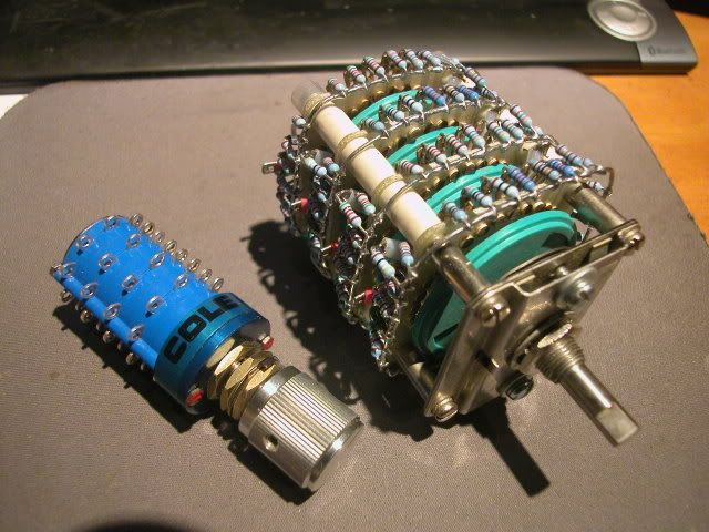
I am thinking about employing this source selector relay board too, but I'm not sure if it will lead to any improvements. (It would disconnect all inputs not being used, including their associated unused ground.)
http://i5.photobucket.com/albums/y177/Midiot/DSCN2571.jpg
=RR=
redrabbit said:
I am thinking about employing this source selector relay board too, but I'm not sure if it will lead to any improvements. (It would disconnect all inputs not being used, including their associated unused ground.)
http://i5.photobucket.com/albums/y177/Midiot/DSCN2571.jpg
=RR=
Hi, =RR=
Good luck w/ your dual coil (dual pulse) MWR relay board. When I started mine I was a bit over ambitious and wanted to couple it with a touch sensor relay switch, bit off more than I could chew though and put it aside. It looks like you have brained it out pretty good I have a few .pdf files on the dual coils if you need them and look forward to hearing how it all turned out.
Best - Stan
These are single coil relays, so I need three per channel...R,L, & Ground. To be operated by a rotary switch.
Ideally, I would have rather found some 3PST...but those are rare in mercury.
=RR=
Ideally, I would have rather found some 3PST...but those are rare in mercury.
=RR=
Grounding for dual mono system
I have one simple question to ask in this related post:
Provided that the L and R ground has already merged in the signal source, is it better to run seperate grounds for each channel through the preamp, power amp to the speaker? I wonder why some diyers merge the L R grounds in power amp despite the amp's design is dual mono.
- Status
- Not open for further replies.
- Home
- Amplifiers
- Solid State
- Grounding Check please (diagram included)