I've seen these type of circuits before. Its just drawn unconventionally that's all.
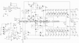
The collectors of the outputs drive the speaker (look at the symbols) with the speaker returned to the centre point of the two large reservoir caps. Signal ground is the little solid black ground symbol in the middle.
The collectors of the outputs drive the speaker (look at the symbols) with the speaker returned to the centre point of the two large reservoir caps. Signal ground is the little solid black ground symbol in the middle.

Hi Mooly
greetings its old technology just want to try it ground connection just cant get it
warm regards
andrew lebon
greetings its old technology just want to try it ground connection just cant get it
warm regards
andrew lebon
Hi Andrew,
this inside out amplifier, has one important thing: Do not ground the transformer secondary. Just connect it to the middle point between the psu capacitors.
Anyway the drawing is quite correctly shows, how to connect the power gnd (earth symbol), and the signakl gnd (solid line).
However I have never heard this type of qsc clones sounding good...
Sajti
Its a QSC and Crown Topology..There are some explanations here.
http://www.diyaudio.com/forums/solid-state/2696-what.html
http://www.diyaudio.com/forums/solid-state/2696-what.html
Was anyone able to simulate this properly?
I've tried several similar amps, including the qsc1700, and none work right, because of the floating supply that doesn't float to the center point at idle.
I'd like to simulate this and see how they fare.
I've tried several similar amps, including the qsc1700, and none work right, because of the floating supply that doesn't float to the center point at idle.
I'd like to simulate this and see how they fare.
This is a RM Audio product which seems to be a serious manufacturer :
RAM Audio - Professional Power Amplifiers
RAM Audio - Professional Power Amplifiers
What I'd like to do is simulate the grounded collector topology.
This seems difficult, with a voltage source floating and not related to ground. This makes the slightest lack of balance in the circuit cause the rails to swing away from a central point, even if grounding the input and trying to balance things out, the rails don't split equally as they should at idle.
Those RAM amps are "borrowing" the qsc grounded collector topology, probably under some kind of arrangement between qsc and them, to allow this, but that topo is basically a qsc one.
It does have a lot in common with the crown topo, which also has the rails swing and an amp output tied to ground, except that qsc has all the output devices with their colllectors grounded. This is a huge advantage for power dissipation, no need to isolate the device cases from anything, as they're all grounded, so there is no need for extra thermal resistance between cases and the heatsinks. This can make for smaller heatsinks and more compact amps, especially with the simpler power supplies.
Now since this topo has the signal passing right through the filter caps, this kind of makes those amps somewhat "safer" for the speakers, as the dc faults are less dangerous, but those amps don't pass dc and having the signal going through the caps can make for more distortion.
I want to find out how to make the simulation work.
qsc clone
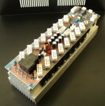
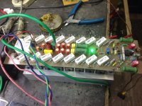
Q-1850 : ?????????????????? PCB : Evens Audio Shoping : Evens Audio & Development
QSC 1850HD works perfectly cloned version
warm regards
Andrew😉
Q-1850 : ?????????????????? PCB : Evens Audio Shoping : Evens Audio & Development
QSC 1850HD works perfectly cloned version
warm regards
Andrew😉
Attachments
What I'd like to do is simulate the grounded collector topology.
This seems difficult, with a voltage source floating and not related to ground. This makes the slightest lack of balance in the circuit cause the rails to swing away from a central point, even if grounding the input and trying to balance things out, the rails don't split equally as they should at idle.
Those RAM amps are "borrowing" the qsc grounded collector topology, probably under some kind of arrangement between qsc and them, to allow this, but that topo is basically a qsc one.
It does have a lot in common with the crown topo, which also has the rails swing and an amp output tied to ground, except that qsc has all the output devices with their colllectors grounded. This is a huge advantage for power dissipation, no need to isolate the device cases from anything, as they're all grounded, so there is no need for extra thermal resistance between cases and the heatsinks. This can make for smaller heatsinks and more compact amps, especially with the simpler power supplies.
Now since this topo has the signal passing right through the filter caps, this kind of makes those amps somewhat "safer" for the speakers, as the dc faults are less dangerous, but those amps don't pass dc and having the signal going through the caps can make for more distortion.
I want to find out how to make the simulation work.
You could model the floating power as batteries. A refinement could include some model too for the capacitive and inductive coupling via the power transformer. Maybe that helps.
You could model the floating power as batteries. A refinement could include some model too for the capacitive and inductive coupling via the power transformer. Maybe that helps.
Actually I have tried doing this before, without any better success.
The part that causes an issue is the fact that a real grounded source topo like this uses a psu with no central point, so the power rails are not symetric and it's just a single +-V rail.
For example for the qsc1700 and its +-93V rails, it's really 186V rail to rail, with no reference to ground.
This causes an issue in the simulations, where the lack of perfect balance in the circuit causes it to swing the rails close to one end instead of nicely idling in the middle.
I'm also trying to figure out how to replace the opamp by a discrete topo. Maybe with a discrete topo the floating rails issue won't be as much trouble, as I suspect the opamp may be a possible source for the issue.
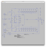
In this schematic that was posted on other threads (see attached), although it "pretends" to be the qsc grounded source topo, it's actually not.
In this schematic, the power supply has a central point, but the real grounded source doesn't.
I did simulations on that one, and this works, because the issue with the lack of central point prevents the wrong float of the rails.
I would like to simulate the real thing, but so far I haven't figured any way of preventing this bad power rail floating issue.
The rails don't stick quite all the way to one end, they keep a few volts away, but that causes the opamp's power to go out of balance, with only one side having the zener set 15V, while the other drops to 5 or 6 volts only.
Attachments
Here is a sim that I made.
I tried replacing the lower diode and zener by one unique zener of the same type as the upper one in the bias string, hoping to better balance it and get closer to bringing the rails on center.
With the input shorted.
And I made the sim run a long way to observe how V(out) settles. It's swinging widely for quite some time, but the rails still won't come to order.
What am I missing?
Attachments
Was anyone able to simulate this properly?
I've tried several similar amps, including the qsc1700, and none work right, because of the floating supply that doesn't float to the center point at idle.
I'd like to simulate this and see how they fare.
I believe three things center the floating supply when the input voltage is zero, which I call "at rest". One is the dual resistor/zener path to power ground in the +-15v power supply path, which draws relatively large equal currents and sets a rough centering. Second is the 47K5 precision resistors across the floating voltage that establish a midpoint, which is treated AC ground for the op amp at rest. The input signal ground is the true reference ground, and sits at the base of the NFB divider. The op amp forces the output transistor collectors to be at the same "AC ground" voltage at rest. Thirdly, the output transistors also do the centering, by at rest sending equal bias currents to power ground. So the advantages of grounding the collectors do have some side effects.
Since this is a DC amp, the input offset voltage of the opamp will be multiplied by the gain of about 41 set by the NFB divider. So there will be a larger offset voltage at the output than in amps that are not DC coupled.
I did a similar design with MOSFETs, grounded drain, but powered my op amp from a separate transformer winding. I did not like drawing the front end power from the floating voltage and from the output via the diodes. Slightly cheaper their way, but I wondered about behavior during faults. Grounding the drains sure helps heat transfer. Thermal resistance is 1/3. Huge benefit.
I think high powered amps are all going digital nowadays, to save cost, weight, and power. So the need for tricks like this are declining. QSC has MOSFET amps and lots of digital control, so I suspect they will move to digital amps.
which I call "at rest".
I called it "idling", but that's basically the same.
One is the dual resistor/zener path to power ground in the +-15v power supply path, which draws relatively large equal currents and sets a rough centering.
Apparently this alone isn't enough.
Second is the 47K5 precision resistors across the floating voltage that establish a midpoint, which is treated AC ground for the op amp at rest.
Which ones are those?
I didn't put any in my sim, but I don't see any in the qsc 1700 schematic either.
Maybe I missed them.
That could be what it needs to center properly...
Since this is a DC amp, the input offset voltage of the opamp will be multiplied by the gain of about 41 set by the NFB divider. So there will be a larger offset voltage at the output than in amps that are not DC coupled.
Perhaps it might be good to have some kind of servo on those.
Slightly cheaper their way, but I wondered about behavior during faults. Grounding the drains sure helps heat transfer. Thermal resistance is 1/3. Huge benefit.
I think it's the biggest advantage, to reduce the needed heatsink size, easier mounting, reduced volume and weight, and there is gain as well on the psu being simpler.
Of course there are also some cons to this, and I don't see this amp passing dc.
The filter caps being sizable makes the low cut off real close to 0hz, but not dc.
In a way it's good for the speakers, and in case of fault in the outputs, I think the caps can mostly protect the speakers from dc.
I think high powered amps are all going digital nowadays, to save cost, weight, and power. So the need for tricks like this are declining. QSC has MOSFET amps and lots of digital control, so I suspect they will move to digital amps.
That may be so, but it's rather out of the diy realm, and I wouldn't mess with that. I'm quite content dealing with analog amps.
- Status
- Not open for further replies.
- Home
- Amplifiers
- Solid State
- grounded collector amp