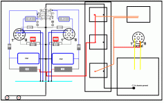
Hi Tim, Nice drawing. You have the right idea...almost. I would make the following change. From the three large main filter capacitors, instead of looping the buss up and around to the input tube area, connect it from the middle filter straight across to the center area near the output tubes. The idea is to keep the buss line short and compact. Use a nice heavy piece of copper wire (#12). Make the chassis connection from the center of the buss to either where it is now or perhaps centered near the tubes. You only need standard hookup wire for this chassis connection btw.
One more observation, why not interchange the PS input capacitor to the upper position. This would slightly shorten the b+ supply line to the tubes as drawn now.
One more observation, why not interchange the PS input capacitor to the upper position. This would slightly shorten the b+ supply line to the tubes as drawn now.
Last edited:
One more observation, why not interchange the PS input capacitor to the upper position. This would slightly shorten the b+ supply line to the tubes as drawn now.
__________________
thanks HollowState!
i would but there's no room
__________________
thanks HollowState!
i would but there's no room
What you need to do is think about the return currents flowing through the ground bus. You want to keep the high return currents from the power supply and power tubes separate from the small signal currents of your input tube. The best hint on the order to hook up the components to the bus is the order they are drawn on the schematic. In other words, grid leak for input tube, cathode resistor input tube, cathode bypassfor same, input grid leak power tube, cathode bias resistor poewer tube and it's bypass cap, then power supply filter capacitors... Keep the big power currents away from your small signal return currents.
Cheers
Cheers
Yes, best practice is to run the ground bus from the main capacitors to the output tubes first, only then to the input tubes, and finally to the input sockets. Basically, the way you wired the B+. This way, you keep the big currents away from the input stage.
If you choose to connect signal ground to chassis (=earth), it can be done either at the input (just use standard RCA sockets) or at the main filter capacitor (then you should use insulated RCA sockets).
Happy building!!!
If you choose to connect signal ground to chassis (=earth), it can be done either at the input (just use standard RCA sockets) or at the main filter capacitor (then you should use insulated RCA sockets).
Happy building!!!
what drawing program did you use? It looks useful.
i just use paint.
- Status
- Not open for further replies.
- Home
- Amplifiers
- Tubes / Valves
- "groundbus" is this right?
