Hi,
I just wonder if this model has a regulated psu supply or unregulated,
I got my rail up and its not regulating.
The rail changes with the input voltage.
then its ok ?=?
best regards
Niklas.
I just wonder if this model has a regulated psu supply or unregulated,
I got my rail up and its not regulating.
The rail changes with the input voltage.
then its ok ?=?
best regards
Niklas.
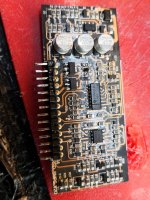
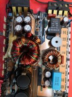
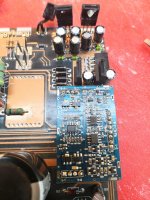
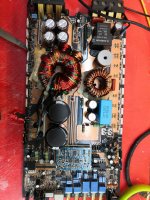
No one knows everything about every amp ever made. There are a lot of clones. Posting good quality photos of the main and any driver boards will significantly increase the chance of getting help.
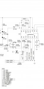
i just have this piece from schematic, which is similar to the one I have. ...
on pin 9 and 10, has a resistor going from each rail to the psu driver board.
i just wonder if i has something with regulation or just checking the rail.
I believe it was some 1.6volt plus minus on pin 9 and 10
on pin 9 and 10, has a resistor going from each rail to the psu driver board.
i just wonder if i has something with regulation or just checking the rail.
I believe it was some 1.6volt plus minus on pin 9 and 10
Attachments
Is that part of the diagram all you have or simply all you're you're willing to post?
The amps using this output type are typically not regulated. Amps with regulated rails typically seen the feedback to one of the error-amps on the driver IC, not to terminals 9 and 10.
The amps using this output type are typically not regulated. Amps with regulated rails typically seen the feedback to one of the error-amps on the driver IC, not to terminals 9 and 10.
Hi Perry, what the owner of the thread meant is that on pins 9 and 10 of the driver board there are 2 resistors (on the side of the amplifier board) that go to the rails, in the schematic, pins 9 and 10, are respectively - / + rail sense and I can guarantee that they are used to make the regulation.Is that part of the diagram all you have or simply all you're you're willing to post?
The amps using this output type are typically not regulated. Amps with regulated rails typically seen the feedback to one of the error-amps on the driver IC, not to terminals 9 and 10.
In the past I have repaired an amplifier that had the same driver board in the power supply and also had the 2 small resistors on the "+/- rail sense" that went respectively to + and - rail of the amplifier and that was regulated.
Also, if you notice well, +/- rail sense, they go to one of the two error amplifiers, so it makes sense.
OK.
So what's the regulated voltage?
Where is it supposed to stop as the B+ is increased?
Can you post the rest of the diagram?
So what's the regulated voltage?
Where is it supposed to stop as the B+ is increased?
Can you post the rest of the diagram?
This can only tell you by trean27, but usually I imagine that if its rail caps are 63 volts, the rail voltage must be around +/- 58v with battery voltage at the maximum allowed and keep roughly that voltage both if the battery voltage drops, both if the rail itself goes down.OK.
So what's the regulated voltage?
Where is it supposed to stop as the B+ is increased?
Can you post the rest of the diagram?
Am I wrong?
It could also be different:
Logically, if the regulation is used to keep the rail as stable as possible, in the absence of load and with the regulation circuit not working, perhaps the rail should go even beyond the value of the rail caps.
Last edited:
Maybe you can but I can't help without knowing more. I can make assumptions but that can provide no definitive answers. If the OP isn't willing to post the diagram and no one else will, I can do no more. The overall amp seems to be common but the regulation in this type of amp is new to me.
Thanks for correcting me on the pin confusion. I misread and thought he was referring to the IC. I wish he would have corrected me earlier.
Thanks for correcting me on the pin confusion. I misread and thought he was referring to the IC. I wish he would have corrected me earlier.
Maybe you can but I can't help without knowing more. I can make assumptions but that can provide no definitive answers. If the OP isn't willing to post the diagram and no one else will, I can do no more. The overall amp seems to be common but the regulation in this type of amp is new to me.
Thanks for correcting me on the pin confusion. I misread and thought he was referring to the IC. I wish he would have corrected me earlier.
I've sent to you an email! 😉
Im sorry for not answering. Perry regarding pin 9 and 10. So the question still is regarding this amp suppose to be regulating or not. I belive you recieved email. Best regards Niklas

- Home
- General Interest
- Car Audio
- ground Zero, gzua 1.1000