Hi guys.
I'm building a stereo amplifier based on LME49830 300W/4ohms RMS boards, and the question is should/is it better to connect the whole aluminum enclosure to mains ground (earth) or is it prefered to be connected to the circuit ground? I always did this last choice in previous projects but you may contribute with your knowledge and experience in this regards. May both mains earth and circuit ground be hooked together as well?
🙂
Well the mains ground is usually connected to the enclosure to protect the enclosure to become connected with the mains if there is a fault in the enclosure.
The enclosure must be connected to mains ground, for safety. Signal ground should be connected to mains ground somewhere in your system.
But not directly, use loopbreaker in amp, in other parts of system do not connect zero volt and ground..Signal ground should be connected to mains ground somewhere in your system.
The usual advice is to make a direct connection between the two grounds in one item, and use loop-breakers everywhere else. In every item a metal enclosure, if present, must be connected to mains ground.
You should not connect the enclosure to signal ground alone, as that provides no safety.
You should not connect the enclosure to signal ground alone, as that provides no safety.
Thanks for all replies 🙂
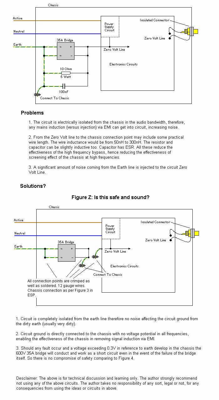
I found this loop breaker circuit. What do you think about it? Do you consider this can be improved with a better arrangement?
I found this loop breaker circuit. What do you think about it? Do you consider this can be improved with a better arrangement?
An externally hosted image should be here but it was not working when we last tested it.
The Mains Earth connection (PE) should be bolted direct to Chassis.
Then the Loop Breaker (Disconnecting Network) can be bolted anywhere to the Chassis. It does not need to and should not share the same bolted fixing as the PE.
The 10r resistor does not need to be 5W.
You can use 10r 600mW or 500mW or 400mW or 250mW.
The 100nF should be a high frequency type, any small ceramic is good enough.
The Bridge Rectifier is shown with the ~ to ~ shorted and with the + to - shorted.
This places both halves of the rectifier in parallel and effectively doubles the current capacity of the diode bridge. i.e. 70Apk @ ~ 800mVf. It should also give a peak transient capability approaching 1000A.
This is my preferred method.
Thanks for your input Andrew. It's much appreciated.
I've been doing a little more research meanwhile, and found this variation of the set up above. Does it make sense regarding earth noise isolation? Seems like it does, but would like inputs about it.

I've been doing a little more research meanwhile, and found this variation of the set up above. Does it make sense regarding earth noise isolation? Seems like it does, but would like inputs about it.

It is a basic safety requirement that all exposed metal parts of the chassis are *directly* connected to earth ground.
Directly as in 'directly'. With nothing in between. No resistor, no diode bridge, no mumbo-gumbo filtering network.
Don't fiddle with safety for the sake of some audiophoolery concerns.
********
In short: The first ground loop breaker you posted is ok, the second is not. Due to safety reasons as well as due to a remarkable amount of audiophile ******** in the explanations.
********
Andreas
Last edited:
Male-cow-excrements. That's hidden behind the asterisks.
@forum moderation: This word is urgently needed in some recent discussions. May it be excluded from the filters?
@forum moderation: This word is urgently needed in some recent discussions. May it be excluded from the filters?
The power line Safety Ground/Protective Earth connection to the chassis should be near the point that the power line enters the chassis. The circuit ground through the bridge should be to the chassis near the I/O jacks.
- Status
- Not open for further replies.
- Home
- Amplifiers
- Power Supplies
- Ground question