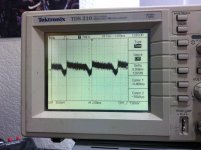
I'm not sure if this is a ground loop or just the 120hz rectified noise making it into my preamp, but either way it makes it all the way out to my amp, with voltage amplification of course.
And I know for sure this is due to my preamp and not the amp because when I hook up another source to my amp, all I get is high frequency white noise at the output, no 120hz noise like I have attached.
I have attached my setup and schematics/layout. Anyone care of help me solve this issue? I know my wiring inside the preamp is a mess, but this couldn't possibly have anything to do with it right?
Attachments
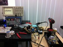
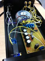
One obvious problem is the wiring. You have LOTS of "enclosed loop area", which makes a great antenna for hum (transmitting or receiving, depending on which wires they are).
Start by twisting tightly together each signal and signal ground wire pair, about 4 turns per inch or more, ALL the way to each end.
Also tightly twist the input AC Mains pair, EVERYWHERE. And do not let them be separated, anywhere, e.g. don't run only one of them to a switch and back.
Also tightly twist each transformer secondary pair.
Tightly twist every wire pair.
On the PCB, all trace pairs must be made so that there is always MINIMAL space between them. Use a ground plane if possible (especially all around the input signal area, separate from the power ground).
Input signal and input signal ground should not connect to anything except final destination (i.e. isolate jacks from chassis). Signal ground should have a spearate ground-return conductor, to the star ground point after PSU caps.
Keep all signal and low-current and low-voltage conductors as far away as possible from, and at a right angle to, all high-current and all very-dynamic (changing)-current conductors and components.
Last edited:
120hz should make you think about poor PSU smoothing rather than induced hum. Ac being rectified twice a cycle.
Last edited:
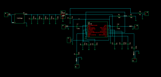
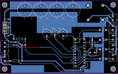
In this case it seems at least as likely that the layout is causing the problem, either by inducing current in loops, and/or, by inducing voltages in ground references, which actually looks like the main problem, here, judging by the PCB layout.
The IC has grounds connected to the bridge rectifier ground, instead of at the downstream end of the smoothing capacitors at the regulator's ground, for example.
Fusion916, on your schematic, all the grounds to the right of the regulator should connect only to the regulator's ground, and not anywhere to the left of that, on the schematic. The regulator's ground should connect only to the right-most capacitor's ground, and not to the left of that. Additionally, some of the grounds to the right of the regulator need to have their own separate conductors going back to the regulator's ground. Any capacitors, after the regulator, that are between power and ground should have their ground conductor go separately from all of the others, back to the regulator's ground. And the input signal's ground should go separately. I would also make the output signal ground separate, back to the regulator ground. I would also be tempted to make each of the smoothing capacitors have its own separate ground conductor going back to the rectifier; or at east the last one before the regulator.
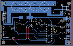
How is this for a new layout?
I don't know if I went overboard on the "single point ground" concept or if this is what is required for a clean noiseless layout.
I was writing while you posted.
That's MUCH better, except move the star ground point so that it's downstream from the last smoothing cao, near the regulator ground. (The charging pulse currents will induce voltages across the ground conductors that go from the smoothing caps to the rectifier. You don't want your audio grounds to all have that voltage bouncing them around.)
ALSO, ANY component that connects to a chip pin should be as close to the pin as possible!
And, you might want some decoupling capacitors, one electro plus a 0.1 uF in parallel at each pin where power enters the chip.
I would probably also have an electrolytic right at the regulator output. But do whatever the regulator's datasheet recommends.
Last edited:
It was exactly the layout. I fabed the new board and the 120hz noise is 100% gone. Amp output is now silent. Thanks guys.
- Status
- Not open for further replies.
- Home
- Amplifiers
- Solid State
- Ground loop/120hz noise in my preamp