1. The first question I have should be straightforward…
When using a ground/loop breaker should the return connection go a chassis point near the safety earth chassis point or to the safety earth chassis point itself?
I've read articles stipulating both ways. I was always under the impression that the safety earth connection should be a dedicated point with nothing else connecting to it.
2. In terms of the group/loop breaker itself I have seen various versions of it. I am trying to understand why there are all these variations and which I want to implement, the pros and cons of each.
Attached is:
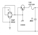
1. the Pass version from a Pearl 2 phono,
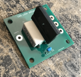
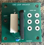
2. the Rod Elliott version (same as pass but with resistor and cap)
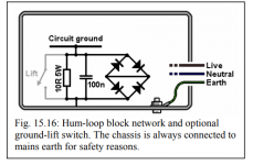
3. Merlin Blencowe version
4. not pictured but my F6 uses a thermistor
When using a ground/loop breaker should the return connection go a chassis point near the safety earth chassis point or to the safety earth chassis point itself?
I've read articles stipulating both ways. I was always under the impression that the safety earth connection should be a dedicated point with nothing else connecting to it.
2. In terms of the group/loop breaker itself I have seen various versions of it. I am trying to understand why there are all these variations and which I want to implement, the pros and cons of each.
Attached is:
1. the Pass version from a Pearl 2 phono,
2. the Rod Elliott version (same as pass but with resistor and cap)
3. Merlin Blencowe version
4. not pictured but my F6 uses a thermistor
Attachments
Perfectly fine to have loop breaker return go straight to safety/chassis earth. Seen it done numerous ways, not just in audio equipment, but big commercial machinery (480VAC stuff).
As to which one is better, I've used NP's, and currently use Rod's version. Even made a PCB for it (totally unnecessary), works great. Put one in every chassis I make, dead silence, no ground loops.
As to which one is better, I've used NP's, and currently use Rod's version. Even made a PCB for it (totally unnecessary), works great. Put one in every chassis I make, dead silence, no ground loops.
Attachments
Thanks for all the information thus far! I have two follow up questions
1. How does a thermistor from audio ground to chassis earth (like in a Pass F6) play in to all these ground breaker/isolation designs? I assume it’s just another piece of resistance (with a little reactance) similar to the other designs.
Any pros/cons of the thermistor?
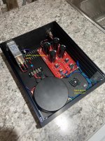
2. I have implemented the ground breaker/isolation in both a phono stage (Pearl II) and a line stage (B1K). In both instances the PSU is in a separate chassis. As such the ground breaker/isolation is in the PSU chassis then a ground wire runs from the PSU chassis to the amp chassis via an umbilical cable.
Any issues?
All I can think of is if there was a fault in the amp (signal) chassis that ground current would have to flow through the umbilical cable back to the ground breaker/isolation then to earth.
1. How does a thermistor from audio ground to chassis earth (like in a Pass F6) play in to all these ground breaker/isolation designs? I assume it’s just another piece of resistance (with a little reactance) similar to the other designs.
Any pros/cons of the thermistor?
2. I have implemented the ground breaker/isolation in both a phono stage (Pearl II) and a line stage (B1K). In both instances the PSU is in a separate chassis. As such the ground breaker/isolation is in the PSU chassis then a ground wire runs from the PSU chassis to the amp chassis via an umbilical cable.
Any issues?
All I can think of is if there was a fault in the amp (signal) chassis that ground current would have to flow through the umbilical cable back to the ground breaker/isolation then to earth.
Hey Nelson, any reason you sometimes go with the thermistor rather than the bridge?It's just another resistor, but has the advantage that its resistance drops when current is passed through it.
In the case of a fault where there is high current, it allows more current through without burning up.
The bridge rectifier in the type of earth-loop-breaker, as shown by MEGA_amp, is used as a diode clamp in case more than 0.6V ever appears across the resistor between the chassis and signal ground. It does nothing in normal operation.
Thermistor type earth-loop-breakers don't require a diode clamp. The thermistor should be rated to bear the brunt of a fault, so that the fuse blows first.
Thermistor type earth-loop-breakers don't require a diode clamp. The thermistor should be rated to bear the brunt of a fault, so that the fuse blows first.
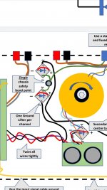
Hard agree with others saying never use a safety-earth terminal connection for anything other than safety earth. Safety earth ground should always be connected directly to the chassis of your device, using wire at least as thick as the power wire, with its own ring terminal, on its own lock-bolt through the chassis.
Where you connect ground for the earth loop breaker is important. You want to avoid any potential differences between signal ground and earth ground, as eddy currents and magnetic fields may be picked up and amplified... for example if your chassis ground and signal ground are connected on opposite sides of a transformer. Generally speaking, put your earth-loop-breaker close to your safety earth ground.
Where you connect ground for the earth loop breaker is important. You want to avoid any potential differences between signal ground and earth ground, as eddy currents and magnetic fields may be picked up and amplified... for example if your chassis ground and signal ground are connected on opposite sides of a transformer. Generally speaking, put your earth-loop-breaker close to your safety earth ground.
Pass Pearl 2 shows a bridge rectifier used as a diode-clamp, but I don't see any connection between earth and signal ground, done to prevent any noise while also providing safety earth. In this configuration, it doesn't matter at all where the diode clamp is installed, there is no connection in normal operation.
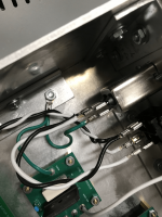
My Pearl II PSU has the audio chassis ground and chassis safety ground configured as such (see picture). The two points are fairly far apart.Pass Pearl 2 shows a bridge rectifier used as a diode-clamp, but I don't see any connection between earth and signal ground, done to prevent any noise while also providing safety earth. In this configuration, it doesn't matter at all where the diode clamp is installed, there is no connection in normal operation.
Attachments
Slight correction.1V2
+/-
two PN junctions in series
")
With rectifier bridge having +- short connected, used for ground loop breaker (GLB), you got two diodes connected in parallel for each voltage halfwave. That way, bridge can conduct twice the current without burning. It is fuse that should and would burn.
I have that type of GLB in all my builds.

- Home
- Amplifiers
- Pass Labs
- Ground breaker/isolation