When browsing through old DIY articles, I found one interesting topology,
that seems was never built, at least not on this forum.
Here is a link to EETimes article "Samuel Groner New Topology",
unfortunately, only part 3 is readable (earlier parts come up with no images),
but never the less, this is the most important part that shows actual schematic of a (headphones ?) pre-amp.
Not sure if this material is copyrighted or not, so I'm not attaching it here.
I think Groner's article was also published in "Linear Audio".
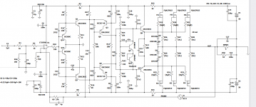
This Groner topology can deliver very high slew rates (over 200 V/us), and very low Thd.
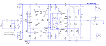
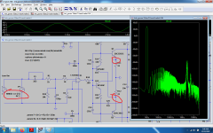
I tried to incorporate this design into a power amp, and to simplify the task, I used op-amp in the input stage,
instead of LTP with current mirror (as in the original design).
Also, increasing current from 1mA to 2mA in the next stage (Q11/Q12) seems to improve stability.
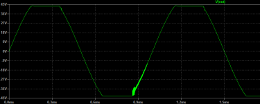
Sim results look good, but one thing that needs improvement for sure, is clipping behavior.
Any suggestions how to do that? Sim file attached.
Update April 2022:
Actual build of the amp, and revised schematic are in post #10
that seems was never built, at least not on this forum.
Here is a link to EETimes article "Samuel Groner New Topology",
unfortunately, only part 3 is readable (earlier parts come up with no images),
but never the less, this is the most important part that shows actual schematic of a (headphones ?) pre-amp.
Not sure if this material is copyrighted or not, so I'm not attaching it here.
I think Groner's article was also published in "Linear Audio".
This Groner topology can deliver very high slew rates (over 200 V/us), and very low Thd.
I tried to incorporate this design into a power amp, and to simplify the task, I used op-amp in the input stage,
instead of LTP with current mirror (as in the original design).
Also, increasing current from 1mA to 2mA in the next stage (Q11/Q12) seems to improve stability.
Sim results look good, but one thing that needs improvement for sure, is clipping behavior.
Any suggestions how to do that? Sim file attached.
Update April 2022:
Actual build of the amp, and revised schematic are in post #10
Attachments
-
 clip1.png6 KB · Views: 313
 -
 fft_1khz.png11.7 KB · Views: 301
 -
 fft_10khz.png13.1 KB · Views: 679
 -
lmk_groner.15dec21.hawk.hexfet.3.asc17.3 KB · Views: 156
-
 lmk_groner.15dec21.hawk.hexfet.3.png45 KB · Views: 714
 -
 thd_10k.png10.2 KB · Views: 495
 -
 thd_1k.png10.6 KB · Views: 299
 -
 olg1.png25.5 KB · Views: 475
Last edited:
Here you go, friend:
Part 1
Part 2
Part 4
No guarantee about images though (EDIT: now I see you already mention this). These EE sites are really bad at migrating their content, not just this one.
Maybe take these URLs and plug them in Internet Wayback Machine, you might get lucky.
I could find some images by clicking on the non-displayed one in Part 1 or 2 I think. No such luck on Part 4.
Maybe Samuel can give you a copy or Jan himself.
Last edited:
It seems that:
A) adding 20pF capacitor between op-amp input/output
or
B) increasing value of R10 from 100 Ohm to 330 Ohm
helps to mitigate clip behavior.
It's still not perfect, but I guess acceptable..
A) adding 20pF capacitor between op-amp input/output
or
B) increasing value of R10 from 100 Ohm to 330 Ohm
helps to mitigate clip behavior.
It's still not perfect, but I guess acceptable..
Really like your circuit.
Does it make any difference giving Q11 and Q12 a bit more voltage by tying the collectors to the rails instead of 0V?
Have you checked out Edmund Stuart's active clamping for clipping?
Active clamp
Paul
Does it make any difference giving Q11 and Q12 a bit more voltage by tying the collectors to the rails instead of 0V?
Have you checked out Edmund Stuart's active clamping for clipping?
Active clamp
Paul
First improvement, but small, on the other hand, i couldn't find a single shematic getting all you need for a high power amp simpler than this one: https://www.diyaudio.com/community/threads/zeta-2-by-lars.360202/. I think using diamond buffers everywhere isn't the silver bullet to escape all sorts of problems in audio.I had simillar arguments about it here: https://www.diyaudio.com/community/threads/improved-diamond-buffer-design.130952/page-6#post-6877207Really like your circuit.
Does it make any difference giving Q11 and Q12 a bit more voltage by tying the collectors to the rails instead of 0V?
Have you checked out Edmund Stuart's active clamping for clipping?
Active clamp
Paul
Attachments
Or here: https://linearaudio.net/articles?f[0]=field_author:388Here you go, friend:
Part 1
Part 2
Part 4
No guarantee about images though (EDIT: now I see you already mention this). These EE sites are really bad at migrating their content, not just this one.
Maybe take these URLs and plug them in Internet Wayback Machine, you might get lucky.
I could find some images by clicking on the non-displayed one in Part 1 or 2 I think. No such luck on Part 4.
Maybe Samuel can give you a copy or Jan himself.
Jan
Does it make any difference giving Q11 and Q12 a bit more voltage by tying the collectors to the rails instead of 0V?
I tried it (collectors going to 15V rails) , and it makes no difference whatsoever (beside power dissipation).
All sim results, including clipping, look the same, as far as I can tell.
So I guess I will settle on R10 being 330 Ohm to fix the clip. I'm going to build a prototype amp of this design.
Dreamth,
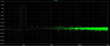
When I tested your change, it seemed like improvement - FFT profile (at 1.2Vpp input signal) was flatter.
Then I noticed, that with your change, idle current of the output devices went down from 70mA to only 5mA.
When idle current is adjusted back to ~70 mA, then all sim results look the same as in the original schematic from post #1.
Am I missing something?
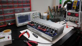
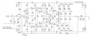
It took over 3 months, but I eventually built this amp.
Have to say it was pain in the neck. Had to revise my original schematic/sim from post #1.
At the end, it turned out that instead of trusting my own simulations,
I should have sticked to the original values proposed by Samuel Groner. Apparently he knows what he's doing 🙂
My biggest problem was that current in the first block of 2 transistor after op-amp was 2mA (sim was showing better results), vs. 1mA proposed by Groner. I wasted lot of time playing with compensation to get rid of oscillations, while the simplest solution was to simply use 1mA instead of 2 mA (R4/R5 changed to 15k (from 6k8)).
Anyway, sim still looks perfect, and amp's results on the oscilloscope also looks good.
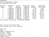
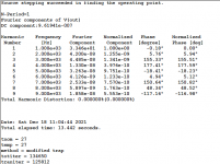
Revised schematic, sim and photos attached. According to the sim, it should be the best amps built by me so far; also the most complex.
As it can be seen from photos, I build a chassis with the mosfet output stage, that can be used for different input/vas boards.
This is the same output stage I already used in numerous other amps, e.g. in the 'unusual amp thread'.
Tested in many amps, and performing very well. Now I can try different input/vas boards, without too much effort.
Not sure if anyone ever built Groner amp (discreet or otherwise), I could not find ANY actual builds on this, and other forums.
Especially given that he never published complete amp - just input and VAS stage are described in the articles.
Interesting thing - I usually use LT1056 op-amp in the sims - because this model is built-in into LTSpice, so it's easy for other people to run the sim,
without installing any extra models/libs.
But in the physical build I usually try TL071 - this op-amp is less temperamental, and rock solid.
In this case, TL071 actually did not work well at all, I had to use actual LT1056.
Of course, will try other op-amps very soon.

Have to say it was pain in the neck. Had to revise my original schematic/sim from post #1.
At the end, it turned out that instead of trusting my own simulations,
I should have sticked to the original values proposed by Samuel Groner. Apparently he knows what he's doing 🙂
My biggest problem was that current in the first block of 2 transistor after op-amp was 2mA (sim was showing better results), vs. 1mA proposed by Groner. I wasted lot of time playing with compensation to get rid of oscillations, while the simplest solution was to simply use 1mA instead of 2 mA (R4/R5 changed to 15k (from 6k8)).
Anyway, sim still looks perfect, and amp's results on the oscilloscope also looks good.
Revised schematic, sim and photos attached. According to the sim, it should be the best amps built by me so far; also the most complex.
As it can be seen from photos, I build a chassis with the mosfet output stage, that can be used for different input/vas boards.
This is the same output stage I already used in numerous other amps, e.g. in the 'unusual amp thread'.
Tested in many amps, and performing very well. Now I can try different input/vas boards, without too much effort.
Not sure if anyone ever built Groner amp (discreet or otherwise), I could not find ANY actual builds on this, and other forums.
Especially given that he never published complete amp - just input and VAS stage are described in the articles.
Interesting thing - I usually use LT1056 op-amp in the sims - because this model is built-in into LTSpice, so it's easy for other people to run the sim,
without installing any extra models/libs.
But in the physical build I usually try TL071 - this op-amp is less temperamental, and rock solid.
In this case, TL071 actually did not work well at all, I had to use actual LT1056.
Of course, will try other op-amps very soon.
Attachments
-
 DSCN0711.jpg373.2 KB · Views: 188
 -
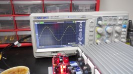 sinus_10khz.jpg318.9 KB · Views: 167
 -
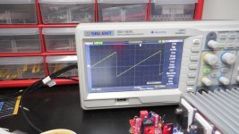 saw.jpg327.4 KB · Views: 155
 -
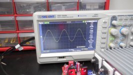 sinus_78khz.jpg329.5 KB · Views: 153
 -
 sinus_100kHz.jpg334 KB · Views: 154
 -
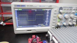 square_1khz.jpg316.8 KB · Views: 161
 -
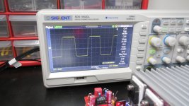 square_34khz.jpg315.4 KB · Views: 152
 -
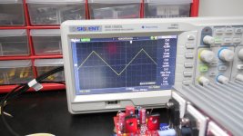 triangle.jpg324.7 KB · Views: 183
 -
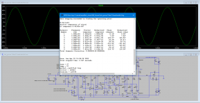 groner_lmk_thd1khz.png42.6 KB · Views: 317
 -
lmk_groner.15dec21.hawk.hexfet.3.asc17.6 KB · Views: 128
-
 lmk_groner.schematic.png42.8 KB · Views: 340
Last edited:
Minek, what do you think about the sound quality of the Groner amp? You never mentioned your listening tests.
Hugh
Hugh
Will do them tomorrow. Was exhausted by several hours of trying this to make this thing work 😁
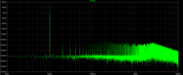
But given that all harmonics are very flat, and below -150dB, I expect clinically clean sound without any signature..
But given that all harmonics are very flat, and below -150dB, I expect clinically clean sound without any signature..
Last edited:
Check out these posts of OS also on Groners topology ! https://www.diyaudio.com/community/threads/slewmaster-cfa-vs-vfa-rumble.248105/post-4664518
Post 9094 onwards !
Post 9094 onwards !
You are right! That's Groner all right. Have to go through that thread, and see if it was actually built!
I wrote something about this kind of output triple and maybe you will find something of interest here.
https://www.diyaudio.com/community/threads/groner-triple.188143/
https://www.diyaudio.com/community/threads/groner-triple.188143/

I didn't know Groner also proposed new kind of output triple. Will try to sim this..I wrote something about this kind of output triple and maybe you will find something of interest here.
https://www.diyaudio.com/community/threads/groner-triple.188143/
One more correction to the schematic.
Bipolar C7 220uF electrolytic has been added (shunt to the ground from the feedback loop).
Without it, DC output offset was about 100mV.
With it, it's 1mV.
Now, in addition to the blue color of the main PCB, red PCB for input/vas, 4 red LEDs per channel, I have 2 big
caps in 'toxic green' color added to it. Christmas time.
Slowly preparing for listening tests later today 🙂
Attachments
- Home
- Amplifiers
- Solid State
- Groner Topology Power Amp