Hi everyone.
I searched for quite a long time, and all references I find, state that grid stoppers help prevent oscillations, not that they could cause oscillations.
I was reciently dealing with a marginally stable amplifier, using global feedback, which I finally compensated quite nicely. Even though not directly related, in the process, I discovered that large value grid stoppers worsened the ringing oscillations (to an input square wave).
The input stage is a common cathode 6DJ8, with 1k grid stopper.
I tried with 33k stopper, soldered right to the socket. Guessing 35 pF input capacitance, this would yield to high Fc 138 kHz. Highs were apparently unaffected. But the ringing oscillations grew in amplitude and settling time. In some particular circunstances on the output stage, it basically oscillated full time.
Going back to 1k stopper in the input stage, solves it and makes a happy amp.
I did add another grid stopper resistor to the output stage, to prevent some mild higher frequency (2 MHz) ringing that sometimes appeared in the square wave test. It also worsens just a little bit the other lower frequency ringing I was talking about before. But it works well enough, and does prevents the 2 MHz ringing.
Why would grid stoppers make more ringing or even oscillations? The main ringin is in the range of a couple of kilohertz, and it is not the same as the output transformer's resonant frequency.
Any idea?
Thanks.
At what frequency were the oscillations? If the frequency is less than a decade or so below the corner frequency of the grid stopper and the grid capacitance of the valve, maybe the extra phase shift caused by a too large grid stopper is just enough to make the overall loop instable.
Was something capacitive driving the cathode of the common-cathode stage? A big resistor in the grid lead makes the input impedance of the common-cathode stage inductive.
Was something capacitive driving the cathode of the common-cathode stage? A big resistor in the grid lead makes the input impedance of the common-cathode stage inductive.
If the ringing is around 2kHz, then a closed-loop with inadequate phase-margin is the most likely problem. As Marcel says, the phase will be rotated by the RC at the input of each stage.
Now that you say the power stage and the input stage can both be made to worsen the low-frequency (2kHz) problem (by increasing the value of the local stopper), that simply adds to the suspicion that it's a loop phase-rotation effect.
Grid stoppers are best reserved for fixing high-frequency self-oscillations (instability of the tube itself). High values of stopper can cause DC problems (from leakage) and potentially HF problems, if the anode load is very difficult.
For stopping 2MHz oscillations, there are a few choices of ferrite beads: for example low-frequency EMC type multi-turn parts, made by Laird, and/or Würth Elektronik. These can often suppress low-HF instability with not-so-much phase-shift at AF, compared to a resistor-stopper. They're designed to be lossy (resistive) at the target noise frequency, but the beads have very low impedance for audio-frequency.
They said MHz, not kHz but didn't mention what the former lower frequency ringing was...
What is the composition of the resistor? Some people report MF types can cause instability, while most people "sing the praises" of Carbon Composition parts.
You could try a ferrite bead on the grid connection, or an RF choke instead and see if that helps?
What is the composition of the resistor? Some people report MF types can cause instability, while most people "sing the praises" of Carbon Composition parts.
You could try a ferrite bead on the grid connection, or an RF choke instead and see if that helps?
<cut> The main ringin is in the range of a couple of kilohertz <cut>
The closed-loop oscillation is this 'couple of kHz' - 2kHz
I experienced a similar issue using 47k grid stoppers on the grids of output stage pentodes (copied from SY's Red Light District). Supposedly useful for minimising blocking distortion, but significantly increased square wave ringing when global NFB applied. I reduced them back to the usual 1k and the problem went away.
Ups. Sorry , I just realised that I said "a couple of kilohertz",  when I wanted to say "a couple of hundreds of kilohertz".
- The ringing frequency was originally just above 300 kHz.
- It became a little bit lower when adding the grid stoppers (200-260 kHz, depending the exact values and setup. I did quite a lot of combinations. But they all fell in that range).
- The grid leak resistor for the 6DJ8 is 470 kohm. I don't think it can be considered a big resistor. The output stage grid leak is well below the maximum value.
- No capacitive driving the cathode. Just the global feedback resistor.
The amplifier has enough stability margin. PM > 60º, GM > 10 dB.
when I wanted to say "a couple of hundreds of kilohertz". - The ringing frequency was originally just above 300 kHz.
- It became a little bit lower when adding the grid stoppers (200-260 kHz, depending the exact values and setup. I did quite a lot of combinations. But they all fell in that range).
- The grid leak resistor for the 6DJ8 is 470 kohm. I don't think it can be considered a big resistor. The output stage grid leak is well below the maximum value.
- No capacitive driving the cathode. Just the global feedback resistor.
The amplifier has enough stability margin. PM > 60º, GM > 10 dB.
I agree. I'll do it when I get some time. By the way, as kodabmx asked, I use metal film and quality carbon film resistors, 2 W (even if just a low wattage is required for this task, as they tend to be less noisy).
It seems that tikiroo has experienced the same. After some more research, I've come across some other people which complain about it too. But I found no explanation. And no book I've consulted mentions this issue with stoppers. Maybe the RC phase shift...
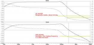
Meanwhile, a simulation of the amplifier clearly shows the effect.
Grid stopper's RC low pass filters add phase shift to the loop gain towards 0º, so the feedback becomes positive sooner. This explains why higher value resistors not only make ringing more pronounced, but also happend at lower frequency.
It seems that tikiroo has experienced the same. After some more research, I've come across some other people which complain about it too. But I found no explanation. And no book I've consulted mentions this issue with stoppers. Maybe the RC phase shift...
Meanwhile, a simulation of the amplifier clearly shows the effect.
Grid stopper's RC low pass filters add phase shift to the loop gain towards 0º, so the feedback becomes positive sooner. This explains why higher value resistors not only make ringing more pronounced, but also happend at lower frequency.
Attachments
Too bad carbon comp resistors absorb moisture and cost many times that of MF types... Luckily, I've never had this kind of instability. I use 300R on preamp tubes though, 1k on power tubes. Why not omit the resistor and retest? It would be interesting to see the comparison plot.
No need for grid stoppers to be purely resistive. There may be some advantage in a little inductance too. You don't have to use CC!
Small grid stoppers prevent RF parasitic oscillation in that stage. Large grid stoppers cause feedback loop instability and treble rolloff, but provide scope for 'tube rolling' to be used as a form of tone control. Hence, typically, hi-fi uses small grid stoppers to keep each stage stable. Guitar amps use large grid stoppers to cope with long wires and poor layout, but not much global feedback.
Small grid stoppers prevent RF parasitic oscillation in that stage. Large grid stoppers cause feedback loop instability and treble rolloff, but provide scope for 'tube rolling' to be used as a form of tone control. Hence, typically, hi-fi uses small grid stoppers to keep each stage stable. Guitar amps use large grid stoppers to cope with long wires and poor layout, but not much global feedback.
Compensation schemes can sometimes be the source of dynamic instability in high voltage circuits. If one end of the compensation is vastly higher voltage than the other, then leakage of the cap may have influence, even with a good quality cap. The solution I found was to use series capacitors with the series join tied to a lower voltage reference by a high value resistor.
Last edited:
What is it that the books do not say? Any decent book will talk about Miller effect, and loop stability. Are you saying that no book puts the two together and explicitly says that large grid stoppers can cause loop instability? A book cannot tell you all the things you should not do; books mainly concentrate on what you should doElerion said:After some more research, I've come across some other people which complain about it too. But I found no explanation. And no book I've consulted mentions this issue with stoppers.
- Status
- This old topic is closed. If you want to reopen this topic, contact a moderator using the "Report Post" button.
- Home
- Amplifiers
- Tubes / Valves
- Grid stopper introduces oscillations