Nothing magical happens with a 377 ohm stopper!!
377 Keebler elves in free space might magically disagree? Or not...
I did clearly state that 377 Ohms was an irrelevant factoid???
Yeah verily, even in my sleep, I most surely did...
But since 377 transforms to different values inside wire. 25 to 800?
Depending exactly where you measure it, and the frequency...
If I was obsessing: Might prefer to error on the low side. A string of
22's could be far broader bandwidth stopper (distributed over length)
than taking chance upon placement of a single lumped stopper hitting
just the right spot at every possible frequency. (ain't never happen)
Braindead answer: Just add a 47ohm near the grid if the rest of the
stopper happens to be greater than 600ohm for other legit reasons.
Last edited:
Thanks, Kevin.
So soldering a 1kohm Allen-Bradley carb comp resistor at the cap may still be a useful step in terms of EMI rejection and stability. Are you a proponent of carb comps in this position, or do you prefer another resistor type? Carb comps are non-inductive for sure, and since the current is negligible shouldn't contribute much noise; on the other hand they are not very temperature stable and can pick up moisture. Something like a Texas Components Z-foil resistor also has very low inductance, but is extremely temperature stable to boot - at $10 each they are pricey but $10 is not so bad when I only need 2 of them. What do you think?
I think the Z foil is gross overkill in this particular application, many swear by carbon comp, but truthfully I have yet to encounter a metal film resistor with enough internal inductance to create a problem particularly with low value resistors, so that is generally what I use. (I know, I know... 😀)
I use 100 - 221 ohm resistors in low level noise sensitive locations, and no more than 1K anywhere else. No observable VHF oscillations/stability issues with D3A/5842/12AX7A/6SN7/EF86 or power tubes like the 300B, 6336A, 6BQ5 or 6550..
Last edited:
There aren't any Keebler elves on my planet.
A stopper does two things:
1. damps any high-Q resonance due to lead inductance and parasitic capacitance, so turns it into a low-Q resonance - less trouble (this can work at grid or anode)
2. in conjunction with the Miller effect (grid stopper only) reduces the HF gain of the stage
In most cases (all audio cases?) a distributed stopper would give no advantage, so just put a resistor at the grid. Don't worry about stubs, antennas, electrons, photons, phonons, excitons or elves.
A stopper much greater than 800ohm will reflect RF rather
than dissipate it. Nothing stopping parasitic standing wave
buildup within grid, lead, Miller, elves, Elvis... If she wants
oscillate, your big lump stopper won't mean a hill of beans.
Regardless stopper might seem with Miller to make low pass
RC from one stage to the next. You forget the grid and lead
is an L. The local LC is what oscillates... If R is too big, its
not a relevant damping participant in that local picture...
Planet or no: Doubt the parasitic Keebler Elvis at your peril!
Iffa you grid stub is oscillating, audio will surely suffer 377.
Don't make me hafta bust out Weekly World News to prove.
Like Radiotron, only page5 girl is better looking.
Then again, just cause grid *can* oscillate, don't mean it will.
But if it does, ask yourself "Was my stopper really damping RF?"
If its clearly too big for one lump, break it up. Or add a smaller
one right next to the grid... Rest of it can be an undistributed
single lump, won't matter. Just RC with Miller like you said...
Last edited:
If a large value stopper reflects RF, then it still stops it getting into the valve so still prevents oscillation. Part of the art of designing RF gear is to know when to use a distributed model and when to use a lumped model. The lumped model is usually appropriate up to around the lower end of UHF - say 300-500MHz. When designing an audio amplifier it is not usually helpful to regard the wire to the grid as being an RF transmission line. About the only exception might be if it happens to resonate at a cell-phone frequency and so cause RF pickup. A metal enclosure is then the best solution.
If a large value stopper reflects RF, then it still stops it getting into the valve
WHAT? Just when I though I was the one making no sense.
You looking at the problem entirely forewards. Reflections
travel both ways. And reflect from both ends of said lump...
Reflection problem is that it traps RF standing wave on the
grid, and prevents it from travelling out in a way that can be
safely dissipated. The grid is the control surface of a rather
effective amplifier. With LC plus travel time for phase shifts,
sustained oscillation is entirely possible.
RF doesn't have to come from outside nor from previous stage.
If any frequency is resonant and undamped at the grid, normal
operation is quite sufficient to get a parasitic started.
Last edited:
The grid itself will resonate at a very high frequency - typically high UHF or microwave. Most valves will have little gain at these frequencies due to transit time effects, so there is little risk of oscillation. Of course, if you use a microwave valve in an audio circuit then you might have to take this into account but why choose an expensive valve which might oscillate when more appropriate ones are available? Not many people use, say, 2C39 as an audio amp.
If the grid is resonant then the ends where the connections are made are likely to be high impedance points so a few K resistance can still damp it. 100's of K might be too high, I agree, but too low a resistance might turn a half-wave resonance into a quarter-wave resonance at a lower frequency.
Almost all parasitic oscillations are caused by resonances in the external circuit, not the valve internals. Most of these can be treated as lumped components, not transmission lines. It is for others to decide which of us is making sense, and which is introducing red herrings.
OK, back to the original topic - I picked up a Tektronix 2205 20MHz oscilloscope and a Tektronix AFG310 arbitrary Function Generator from work and hooked it all up last night. I needed to make a couple BNC to RCA cables but other than that it all worked out pretty well.
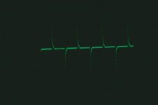
The pictures below show, in order, a 2Kohm square wave with only the oscilloscope loading (no resistor across transformer +/-) a 10kohm square wave with no loading other than the oscilloscope, and the same 10kohm square wave with 2.2kohm loading across the transformer.
The 10kohm square wave shows ringing without a load resistor; adding the 2.2kohm resistor seems to solve that problem nicely.
Attachments
Some additional scope pictures.
The first is a 2kHz square wave with the 2.2kohm load resistor - I think it looks pretty good.
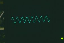
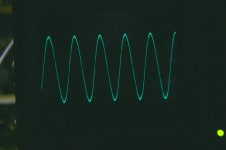
The second is a 2kHz sine wave, and the third is a 20kHz sine wave. Also looking pretty good I think.
Of course the ultimate test is listening. After I took all the scope shots I hooked it all up and listened for ~6 hours. The preamp sounds EXCELLENT with the LL1674 transformers and the 2.2kohm load resistor. The biggest improvement I notice over stock is in the details, especially bass details; it is now very easy to follow the bass player through an entire song.
By the way, while I was in there I did some lead dressing to clean things up a bit. This dropped the hum level down to ~1mV; hum is conmpletely inaudible, even with my ear to the speaker!
The first is a 2kHz square wave with the 2.2kohm load resistor - I think it looks pretty good.
The second is a 2kHz sine wave, and the third is a 20kHz sine wave. Also looking pretty good I think.
Of course the ultimate test is listening. After I took all the scope shots I hooked it all up and listened for ~6 hours. The preamp sounds EXCELLENT with the LL1674 transformers and the 2.2kohm load resistor. The biggest improvement I notice over stock is in the details, especially bass details; it is now very easy to follow the bass player through an entire song.
By the way, while I was in there I did some lead dressing to clean things up a bit. This dropped the hum level down to ~1mV; hum is conmpletely inaudible, even with my ear to the speaker!
Attachments
OK, back to the original topic - I picked up a Tektronix 2205 20MHz oscilloscope and a Tektronix AFG310 arbitrary Function Generator from work and hooked it all up last night. I needed to make a couple BNC to RCA cables but other than that it all worked out pretty well.
The pictures below show, in order, a 2Kohm square wave with only the oscilloscope loading (no resistor across transformer +/-) a 10kohm square wave with no loading other than the oscilloscope, and the same 10kohm square wave with 2.2kohm loading across the transformer.
The 10kohm square wave shows ringing without a load resistor; adding the 2.2kohm resistor seems to solve that problem nicely.
Obviously, the frequencies stated in the post quoted above should be in kHz, not kohm. That's what I get for posting before my morning coffee!
When I speak about the square wave response looking good in the above posts, I'm referring to the ringing and damping of such by a load resistor.
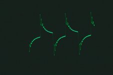
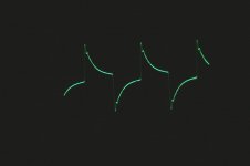
I'm curious as to why the waveform reproduced by the O-scope does not look like a square wave, however. It instead appears to be a derivative of a square wave. Do I have a setting on the O-scope or function generator incorrectly set?
The preamp sounds great, but the shape of the plots is bugging me. Any help?
.
Last edited:
Do I have a setting on the O-scope or function generator incorrectly set?
Yes. Take a photo of the whole face of the scope with the controls showing and someone will no doubt spot the incorrectly-pressed button (probably a subtraction feature).
Ok, I'll need to do that when I get home. I am very happy with the sound of the preamp, however, so I don't know if I'll disconnect everything to re-run the test.
Is it valid to say that the conclusions about the ringing and the damping of such using a load resistor are still valid? My listening tests do indicate that the 2.2K resistor load does sound better than no load (the preamp has a load selector swith on the back that lets me easily switch between 0, 2.2kohm, 1kohm, 670ohm, etc. loads). No load is harsher sounding, like a bad CD.
Is it valid to say that the conclusions about the ringing and the damping of such using a load resistor are still valid? My listening tests do indicate that the 2.2K resistor load does sound better than no load (the preamp has a load selector swith on the back that lets me easily switch between 0, 2.2kohm, 1kohm, 670ohm, etc. loads). No load is harsher sounding, like a bad CD.
I'm curious as to why the waveform reproduced by the O-scope does not look like a square wave, however. It instead appears to be a derivative of a square wave.
Because you are shoving it through coupling element with HP characteristic.
What the heck is "2Kohm square wave" and "10kohm square wave" ? (mentioned in post #28)
What the heck is "2Kohm square wave" and "10kohm square wave" ? (mentioned in post #28)
I corrected that in the post following it - kohm should read kHz, so it should be a 2kHz and 10kHz square wave. It was too late to edit it when I noticed it.
Could you please explain further the "shoving it through a coupling element with HP characteristic" comment?
.
After further thinking, I'll bet the square wave problem has to do with the cables I'm using. Since the scope has a 1Mohm input impedance, the capacitance in the cables will work with that impedance to form an effective high-pass filter.
The scope was in a drawer in the lab for the past 5 years, having been used for some RF sensor work previously, and I just grabbed some of the coaxial cables that had BNC connectors on them and made them work by cutting off one end and soldering on an RCA plug. Coax has a lot of capacitance and is really meant for RF work.
I will make some new cables and I bet that solves the measurement issue.
.
...It looks like the "ringing" I'm seeing may be purely the result of the crappy sound card!
What you need is an audio interface for your computer with, say 4X the bandwidth of the device you are testing. These computer interfaces are common in even home recoding studios and cost starting at about $200. Look for one that can sample at 196K samples per second at 24-bits per sample.
Hi,
Well put.😎
Normally a well designed audio circuit should not need any gridstoppers.
Should they be needed keep them small both in value and size. 1/4 Watt should suffice as should a couple of hundred Ohms.
In amplifiers the gridstopper resistor may take on a different role as it can prevent the grids of the ouput tubes from blowing up.
In those cases an Ohmic value ranging from 1K to 100K may be helpful.
Again, this band aid should not be required in a well designed amp....
Cheers, 😉
If a large value stopper reflects RF, then it still stops it getting into the valve so still prevents oscillation. Part of the art of designing RF gear is to know when to use a distributed model and when to use a lumped model. The lumped model is usually appropriate up to around the lower end of UHF - say 300-500MHz. When designing an audio amplifier it is not usually helpful to regard the wire to the grid as being an RF transmission line. About the only exception might be if it happens to resonate at a cell-phone frequency and so cause RF pickup. A metal enclosure is then the best solution.
Well put.😎
Normally a well designed audio circuit should not need any gridstoppers.
Should they be needed keep them small both in value and size. 1/4 Watt should suffice as should a couple of hundred Ohms.
In amplifiers the gridstopper resistor may take on a different role as it can prevent the grids of the ouput tubes from blowing up.
In those cases an Ohmic value ranging from 1K to 100K may be helpful.
Again, this band aid should not be required in a well designed amp....
Cheers, 😉
Your square waves look like those on my 2246 Tektronix scope when the 10x probe's "trimmer screw" is not adjusted properly.
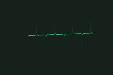
Well, I figured it out! The channel 1 output button on the function generator was a little sticky, and only a very small portion of the signal was getting to the preamp. I worked it a few times and now I'm getting the full signal from it.
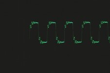
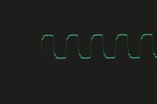
Here are the traces for a 20kHz square wave with no transformer resistor loading, 2.2kohms loading and 1.5kohms loading.
What do you think?
Here are the traces for a 20kHz square wave with no transformer resistor loading, 2.2kohms loading and 1.5kohms loading.
What do you think?
Attachments

- Status
- Not open for further replies.
- Home
- Amplifiers
- Tubes / Valves
- Grid Stopper Advice - Graphs Included!