When the leads are wrapped around a solder terminal like a boa constrictor and soldered you have to adopt VC tactics to get in and get out... Don't let the children watch.
Agreed!!! Glad to know I'm not alone
I measured tonight, I got -.5v across the grid load resistor with my dvom. I got -.6v with my meter in place of the resistor. Seems to me that 5m is sufficient to prevent the bias voltage " to drain off". Makes sense I guess since I saw some old fender amps using 5m resistor in that position. The output of the stage proved to be not real linear. Sine wave appear somewhat distorted
I measured tonight, I got -.5v across the grid load resistor with my dvom. I got -.6v with my meter in place of the resistor. Seems to me that 5m is sufficient to prevent the bias voltage " to drain off". Makes sense I guess since I saw some old fender amps using 5m resistor in that position. The output of the stage proved to be not real linear. Sine wave appear somewhat distorted
Measuring the anode voltage is a more rugged approach to what the grid bias is. If you swap a grid leak resistor for a meter's resistance, and the anode voltage remains constant, then the meter is going to indicate the bias voltage accurately. Check where the operating point is on a loadline.
Remember that grid leak current varies as the bias voltage approaches 0V, and is likely changing quite rapidly within 1V of zero.
Measurements of low voltage levels using large series resistance probing is going to require lab grade metering and a bit of care, especially in a mains powered circuit.
Remember that grid leak current varies as the bias voltage approaches 0V, and is likely changing quite rapidly within 1V of zero.
Measurements of low voltage levels using large series resistance probing is going to require lab grade metering and a bit of care, especially in a mains powered circuit.
I measured tonight, I got -.5v across the grid load resistor with my dvom. I got -.6v with my meter in place of the resistor. Seems to me that 5m is sufficient to prevent the bias voltage " to drain off". Makes sense I guess since I saw some old fender amps using 5m resistor in that position. The output of the stage proved to be not real linear. Sine wave appear somewhat distorted
Good work. May we presume you were imposing a 1 to 10 millivolt sine wave on the input? Anything larger than about 100 mv and of course the stage will be nonlinear!
GoatGuy
Last edited:
I'm sure my input voltage was more than 10mv, probably why it looked the way it did. It appeared somewhat clipped on the positive half of the waveform. I was thinking it might have been due to the very large plate resistor. It's a neat arrangement that I hope to play with in the future in some custom builds
Can any one help with the relationship with the value of the capacitor? I would like to reduce the 0.047uF cap to decrease bass, but I don't want to kill the bias affect.
Decreasing the coupling cap surely won't affect bias. Increasing it might do that.
Best regards!
Best regards!
The cap value may affect the attack and decay response.
Is your issue with too much bass related to what gets through to the output stage and speaker? If so then perhaps better to manage that after the first stage, or at the first to second stage coupling.
Is your issue with too much bass related to what gets through to the output stage and speaker? If so then perhaps better to manage that after the first stage, or at the first to second stage coupling.
A consideration is also sensitivity to induced noise. Using a small capacitor as a l.f. filter, leaves the grid at a high enough input impedance to pick up induced stray fields. In that sense it makes sense to use a high enough coupling capacitor to keep the input impedance low and go to some other RC coupling to reduce l.f. pickup.
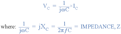
You can use online calculator to find the value of the capacitor for your bass frequency, in respect to the grid bias resistor's value. It is easier than to calculate. 🙂
Capacitor Impedance Calculator - Electrical Engineering & Electronics Tools
Capacitor Impedance Calculator - Electrical Engineering & Electronics Tools
Attachments
Hi,
I have written a little article about grid leak bias, if anyone is interested it can be found here:
Grid Leak Bias or Contact Potential Bias. – tubes
Any comments are appreciated
I have written a little article about grid leak bias, if anyone is interested it can be found here:
Grid Leak Bias or Contact Potential Bias. – tubes
Any comments are appreciated
tmi, nice read and results.
Were you able to plot a sample characteristic curve on the plate characteristics for varying Rg, as a practical example of setting up an operating point ?
It may also be worth elaborating on the change in plate mean voltage when signal is applied, and when clipping would start to impose itself.
Many of us relate more to guitar amp applications than hi-fi, but from both perspectives, the influence of a step in input signal level would be worth expanding on and having an awareness of how noticeable the rise/fall (or attack/decay) response is.
Last edited:
Due to some high risk of blocking distortion, grid leak bias cannot be recommended in a guitar amplifier.
Best regards!
Best regards!
Due to some high risk of blocking distortion, grid leak bias cannot be recommended in a guitar amplifier.
Back in 1974 I used 4.7 MOhm with 6J32P in a guitar amp. The sound was gorgeous!
Why should be any difference between grid and cathode biases for the same current, since the voltage between grid and cathode would be the same? The only difference is, they are obtained from different currents.
Thanks for all the responses. Very useful article for me toriversen. So it looks I could change the cap value, but because of the high 3M3 Rg, the cutoff point is 1Hz so I would have to change it by about /100 to be useful so might well be too small then. Might have to leave it.
The grid leak bias is in a Carlsbro PA60, so it's not expecting to have high amplitude inputs I guess.
The grid leak bias is in a Carlsbro PA60, so it's not expecting to have high amplitude inputs I guess.
The mic it was intended for was probably a low output crystal or low output ceramic mic.
There is probably not quite enough gain, but I bet that most 600 Ohm dynamic microphones could be connected directly between the control grid and cathode of a 12AX7 and work reasonably well.
There is not likely enough voltage to draw significant grid current from the low impedance 600 Ohm source.
However, using it that way, would not have the advantage of a typical 600 Ohm mic circuit.
One that uses an input transformer, and gives very good common mode hum reduction.
Toriversen,
Excellent! I am keeping a copy of this in my files, as real data for this mode of operation is scarce. My few comments and somewhat different approach here are not meant to detract in any way from your work. (I cannot find any shortcoming in what you did.)
But the first thing I felt is that I would rather have compared distortion and other performance at the same output signal voltage, not signal input. The higher distortion that you got for this mode puzzled me since I previously had seen measurements showing the opposite under certain conditions. (That was w a y back for me; I no longer have those figures.) From memory, at the time, the author wrote that working in optimal class A all the time, i.e. as close to grid-drawing-current as is healthy, was a better condition than with a small signal deep into negative bias for g1 - something like that. (I thought this was from an old RCA Tube Manual, but could not find it.)
I have thus used the grid-leak bias sometimes with no apparent ill result. In a present 100W stereo power amplifier I again do, simply because my input pentode is an ECF82. [Some of these things, being a mainly r.f. tube, picked up hum through the heater-cathode proximity, which I could only cure by earthing the pentode cathode.] Having access to a spectrum analyzer now which I didn't have then, I could perhaps re-examine.
I have also read elsewhere (Rod Elliott) that grid leak bias has no place in hi-fi; perhaps. I feel it would depend on circumstances. (There is an RIAA topology using a pentode input, triode output mode, thus necessitating feedback to the pentode cathode (my favourite tube topology).
But thanks again to Toriversen.
Johan,
Your experience with hum in an ECF82 seems to correlate with the DC heating remark found in the 6AC7 datasheet.
Given its 9 mA./V. gm, the 6AC7 might be quiet enough for 1st gain block duty in a phono preamp.
Your experience with hum in an ECF82 seems to correlate with the DC heating remark found in the 6AC7 datasheet.
Given its 9 mA./V. gm, the 6AC7 might be quiet enough for 1st gain block duty in a phono preamp.
I define "deep into negative bias" as "Very near cutoff". Very near cutoff is generally recognized as non-linear. Very near zero bias is known to draw grid current. Grid current reduces the impedance of the grid, the signal source has to drive that lower impedance.
Generally, tubes are less noisy with some plate current in them, not so at near cut off. Generally, tube with high gain is going to have reduced dynamic range, if it is operated either near cut off, or near zero bias. Many of us choose to operate somewhere in the middle between those two extremes. "All Generalizations have exceptions" - Me Some small signal tubes have spiral filaments in the cathodes. One advantage is the reduction of hum.
Generally, tubes are less noisy with some plate current in them, not so at near cut off. Generally, tube with high gain is going to have reduced dynamic range, if it is operated either near cut off, or near zero bias. Many of us choose to operate somewhere in the middle between those two extremes. "All Generalizations have exceptions" - Me Some small signal tubes have spiral filaments in the cathodes. One advantage is the reduction of hum.
Exactly. The higher is the negative voltage on the grid in respect to cathode, the more pitch between grid wires matters, looking like many different tubes in parallel, so differences more and more play the role decreasing linearity.
- Status
- Not open for further replies.
- Home
- Amplifiers
- Tubes / Valves
- Grid leak bias, how does it work?