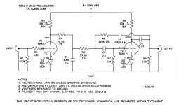
Currently enamoured with Joe Tritschler's Tpad phono stage , described in his article , I thought it would be interesting to try the idea with subminiature dual triode 7963 having roughly the same transconductance and gain as the original 5842 when both sections are paralleled.
My question here is about the output stage bias that due to grid current is running with allowable current but very slight positive bias. The original design with 5842 has a grid voltage of .002vdc for a current of about 2nV. The 7963 equivalent runs at 1.7vdc and 1.7uA. Quite a difference , putting that section on the A2 side of things.
Incidentally , I did build two channels of this circuit and measurements are pretty much identical .
My question here is really , how to pull it back to the Vgk≈-1.2V area of operation as the first stage is. I can't lower the grid resistor by much as the impedance of the circuit feeding it is pretty high. Would you simply increase Rk (which starts to ask for bypass cap) or perhaps a 1.8 - 1.9 V drop Led ?
Your thoughts would be appreciated.
Thanks
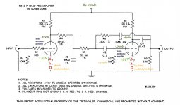
Attachments
Last edited:
Are you sure that C2 isn't leaking?
If the two 7963 sections are paralleled, that 1M maximum grid resistance rating becomes 500k.
If the two 7963 sections are paralleled, that 1M maximum grid resistance rating becomes 500k.
No, I wasn't sure about C2 but it was a 630V rated orange drop so I just assumed . . . .
Reading your post I went and tried a few things.
Changed out the cathode resitor for LED .Cathode went to 2.1V and grid went to 2.39V.
Tried a CCS and that pushed the grid V up even higher. So starting to pull C2 to try another I found a hidden mistake , connecting the grid stopper to the input of C2 (Junction of R5, R6 and C2. I'm amazed that V2 didn't get damaged.
Result is now approx 90V on all the plates and 1.155v on the cathode resistors. Grid voltage of the second stage goes up to 20mV on start-up and then down to .2mV (.2nA) after a minute or so.
Your input helped as usual. My mistake again, nice to know that things are still normal : ) and Ohms law still rules.
Thanks

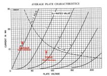
If the plate impedance, rp, of a 5842 . . . is not the same as the paralleled 2 plates impedance, rp || rp, of a 7963, then . . .
The RIAA equalization will be incorrect.
Which is more or less true, depending on rp.
Plate impedance, rp, is a variable, it depends on the tube type. And it depends on the quiescent current of that particular tube type.
The RIAA equalization will be incorrect.
Which is more or less true, depending on rp.
Plate impedance, rp, is a variable, it depends on the tube type. And it depends on the quiescent current of that particular tube type.
Yes, it appears that R4 should be increased by around 600R, presuming the original design was accurate.
Really, RIAA circuits should use 0.1% components (for both R and C) for predictable and consistent performance.
So it isn't hard to believe that an error as large as 1.5% will make a significant difference, perhaps 0.2dB or so.
To readjust the new tube's rp back to the original design curve, the circuit needed ~600R from a quick "back of the envelope" calculation.
But I haven't checked the original curve to see if it was actually optimized in the first place. Maybe you can iterate the value
of the added resistor in SPICE and find the "right" value.
Bear in mind that the physical circuit will have different RC values due to their tolerances, and may or may not have improved response
with the "right" value. One thing I would suggest however, is connecting C3 to the other end of C4 instead.
Well , you know your beans !
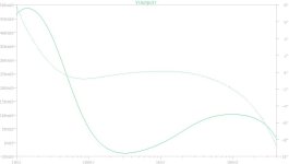
I thought that my 7963 version really sounded muffled and also somehow sucked out in the upper mids. Not having a model for the 7963, putting your +600Ω adjustment of R4 to 39.8K into the 5842 spice showed clearly in first image that it might possibly benefit the twin triode version.
Following that, I went ahead and added a 620Ω resistor, which does bring up the mids and highs but there is clearly still an imbalance between high and low, with an irritating lift at kick drum and bass frequencies not found with the 5842 circuit. No time to set up bench measurements yet.
For C3, I had read that connected in series with C4 wouldn't have much of an effect and the while the sim seems to bear that out I went ahead with your suggested change anyway. I think it might have sounded a little clearer, but there were enough other problems with the sound that after the first moment's good impression the effect was swamped by the sound's other shortcomings.
(By the way, JT did have it connected to plate in his first article but in the course of further developing the circuit ended up with it connected to C4 out in his revisit 7 years later. )
Anyway , more work to do but first to go through Borbely's article and try to understand how JT got from that complex circuit to one with just two triodes. I won't waste your time on this subject until I've done some reading.
Thanks
Attachments
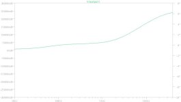
The 3180 us bass correction depends on the mu of the second valve, as the lowest correction cut-off happens where the feedback loop runs out of loop gain. Some dubious websites I found claim that the 7963 has a mu of 40 and the 5842 has a mu of 50.
And you frequent those sorts of websites do you? 😎 (This is the closest I could find for an emoji representing the state prosecutor.)
As you say, the 7963 sheet gives 40.
Raytheon and Western Electric say 43, Ericsson says 43, or 44 with their interesting bias scheme and only the CSF/Thomson datasheet says 50.
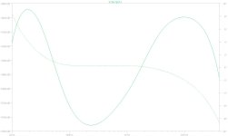
Following your prompt I spent the last five minutes fiddling with values for mu (response graph attached) , C3 and R6. Clearly, interdependence rules and I have a lot to learn before I know how to control the output response at will. Maybe I should just go buy a Sony.
As you say, the 7963 sheet gives 40.
Raytheon and Western Electric say 43, Ericsson says 43, or 44 with their interesting bias scheme and only the CSF/Thomson datasheet says 50.
Following your prompt I spent the last five minutes fiddling with values for mu (response graph attached) , C3 and R6. Clearly, interdependence rules and I have a lot to learn before I know how to control the output response at will. Maybe I should just go buy a Sony.
Attachments
Last edited:
- Home
- Amplifiers
- Tubes / Valves
- Grid Current moving bias . Best solution ?