Hi Dirk,
And what about the -notorious- hum sensitivity of plate chokes?
All of my experiments the 50Hz, 100Hz components are larger (sometimes 20dB!) in plate choke circuits, than other active (CCS, gyrator) load ones.
Yeah, maybe so. I don't know.
Don't trust the noise models for tubes. It's worth reading Merlin Blencowe's recent JAES article.
It's just a relative comparison, so I assume the model I'm using is ok with that.
I do not have access to JAES articles, since I am not a member. Can you summarise the results for us please?
It seems that if these kinds of chokes are very sensitive to hum pickup, then a toroidal core should probably be used. I don't know if anyone is making them.
It's just a relative comparison, so I assume the model I'm using is ok with that.
I do not have access to JAES articles, since I am not a member. Can you summarise the results for us please?
I absolutely would not assume that.
In a nutshell, Merlin experimentally showed that ENR specs are wildly incorrect at audio, 1/f corners were all over the place, noise did not monotonically decrease with current, and sample-to-sample variation is huge.
Let's do a quick calculation of the noise contribution of a CCS. Jung measured the FET cascode to have 14nV/rt Hz noise current. For a D3a with a 2k5 rp and mu of 85, that translates to (14pA)(2500R)/85 = 0.4nV/rt Hz voltage noise. This is an order of magnitude lower than the tube noise for a really excellent tube, and is uncorrelated (thus adding as power).
Hi,
You won't like it but even though ENR noise figures for a ECC83/12AX7A are nowhere to be found AFAIK, this tube is remarkably quiet at LF.
Relatively more so than some VHF tubes at LF.
Still, regardless of the excellent research by Merlin B., it is not a bad idea to investigate specced low noise valves.
These often incorporate the latest tech and in more cases than not, IME, also offer outstanding LF performance.
I won't list them since that would just quadruple the already ridiculous asking price.
To return to topic: Is a CCS all that quiet? I don't think so but then that's not why I'd use it for, if at all, in the first place.
Horses for courses.
Is a choke a perfect plate load? No.
Once again, horses and all that....
Sometimes it is wiser to pursue the perfect reproduction of music rather than the perfect reproduction of imaginary perfection.
Ciao, 😉
I absolutely would not assume that.
I think you misunderstand. I kept the current and voltage for the tube the same in each version. Why wouldn't that be good enough?
I think you misunderstand. I kept the current and voltage for the tube the same in each version. Why wouldn't that be good enough?
Because the model's noise performance is not anything like the real device, and is usually quite optimistic so that in many cases the results are misleading.. As far as I know the equivalent voltage/current noise generated by a typical tube is not modeled (no noise sources in the model) at all, so you will only see the noise contributed by external devices connected to the pins.
Because the model's noise performance is not anything like the real device, and is usually quite optimistic so that in many cases the results are misleading.. As far as I know the equivalent voltage/current noise generated by a typical tube is not modeled (no noise sources in the model) at all, so you will only see the noise contributed by external devices connected to the pins.
Well, I do not understand the macro language of spice models, nor do I have a complete understanding of how the models work, but as far as I can see, there are no "noise generators" in this model of the SA970 transistor either:
.MODEL 2SA970 PNP (IS=9.98557F BF=477.115 NF=965.739M VAF=64.7 IKF=116.959M
+ ISE=2.13187F NE=1.27276 BR=385.069M IKR=308.018 ISC=13.4194P RC=7.03858
+ CJE=2P MJE=500M CJC=19.116P VJC=749.982M MJC=498.685M TF=1.49138N XTF=500M
+ VTF=10 ITF=10.0655M TR=10N )
Or for this model (by the manufacturer) of a 15mA CLD:
*********
*==========================================================
* CCL and CCLH Series of Current Regulator Diodes
* Central Semiconductor Corp.
* IsSpice and SPICE3 Compatible Models
*
* These models were developed for Central Semiconductor Corp. by:
* AEI Systems, LLC
* 5777 W. Century Blvd. Suite 876
* Los Angeles, California 90045
* Copyright 2002, all rights reserved.
*
* This model is subject to change without notice.
* Users may not directly or indirectly re-sell or
* re-distribute this model. This model may not
* be used, modified, or altered
* without the consent of Central Semiconductor.
*
* For more information regarding modeling services,
* model libraries and simulation products, please
* call AEi Systems at (310) 216-1144, or contact
* AEi by email: info@aeng.com. ::AEi Systems - Analog HEAVY Lifting::
*
* Revision: B
*==========================================================
*********
*SRC=CCLH150;CCLH150;Diodes;JFET Regulator;100V 15.0mA
*SYM=CRDIODE
.SUBCKT CCLH150 1 2
*Connections Anode Cathode
JFET 1 2 2 CCLH150J
.MODEL CCLH150J NJF VTO=-8.48 BETA=.33M LAMBDA=0.1M
+ IS=100.58F PB=.8 FC=.5 RS=120 RD=3 CGS=1.57P CGD=9.43P
.ENDS
So, unless you have proof that a noise model is required, then you're just expressing an opinion. Please show me where a "noise generator" is required in a spice model in order to obtain accurate noise results in spice simulations. Thanks.
It also seems self evident to me that the resistive component of noise would be accurately determined, since the software knows the internal resistances of the device and the current flowing through each of them. I do not know much else about how the software works, do you? Please show me an accurate spice model that has a noise source built into it. Thanks.
The point is that there aren't any, and if there were, they wouldn't be applicable to the majority of the population of a tube type. Get some parts, some solder, and some test equipment- that's the only way you're going to get any real handle on the factors that affect noise in tube circuits.
The point is that there aren't any, and if there were, they wouldn't be applicable to the majority of the population of a tube type. Get some parts, some solder, and some test equipment- that's the only way you're going to get any real handle on the factors that affect noise in tube circuits.
So, are you saying that you NEVER use any kind of spice simulation to guide you in making designs? Maybe we should consult someone who actually knows the details about spice and noise measurement before wasting a lot of time and money on building things that won't work. I used to build things all the time, and had a pile of old test gear. I've learned more through using spice than I ever learned that way.
So, also, are you saying that these solid state models I put up are completely inaccurate regarding noise measurement also? What, exactly, are you saying anyway and why do you keep arguing about this?
Finally, do you know of ANY spice models for transistors or tubes that have noise sources embedded in them? If not, why not? and why don't they?
I am not convinced that a noise generator is required in a spice model of a transistor or of a vacuum tube. Show me the proof that one is required or just stop talking. Thank you.
So, are you saying that you NEVER use any kind of spice simulation to guide you in making designs?
For tube noise and distortion, no I don't. Passive components and semiconductors are much more amenable to accurate simulation (their operation is much less dependent on physical structures and more on fundamental physics), and that's where I use it.
I "argue" about it because I've actually done the experiments and collected the data. If your model indicates things which don't correspond to reality, the model is wrong, not reality. You really need to read the literature, AES member or not.
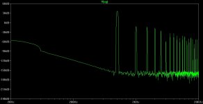
Dirk, what do you think about the difference of this pictures?
The schematic: D3a (175, 9.5mA, B+ is 350V), green LED bias, cascode CCS as plate load, 100nF coupler, 300B grid as the loading, 70V RMS on the 300B grid.
Dirk1.jpg (green) distortion is 0.56%.
The schematic: D3a (175, 9.5mA, B+ is 350V), green LED bias, cascode CCS as plate load, 100nF coupler, 300B grid as the loading, 70V RMS on the 300B grid.
Dirk1.jpg (green) distortion is 0.56%.
Attachments
Dirk, what do you think about the difference of this pictures?
The schematic: D3a (175, 9.5mA, B+ is 350V), green LED bias, cascode CCS as plate load, 100nF coupler, 300B grid as the loading, 70V RMS on the 300B grid.
Dirk1.jpg (green) distortion is 0.56%.
I'm sorry, I don't understand the two different FFT results? Which one is which now?
The cascode CCS is NOT my design! it is taken directly from Sy's "His Master's Voice" first stage.
About vacuum tube noise, it appears that having a "noise generator" in the macro model is completely unnecessary unless you want to simulate flicker noise. Thermal noise in tubes is given by the function:
Rn=2.5/Gm
If the device is a pentode, then we have to add partition noise to the above equation:
Rn=(2.5/Gm)*(1+8(Is/Gm))
It's a simple mathematical function, so what's the problem? I don't get it.
Rn=2.5/Gm
If the device is a pentode, then we have to add partition noise to the above equation:
Rn=(2.5/Gm)*(1+8(Is/Gm))
It's a simple mathematical function, so what's the problem? I don't get it.
It's a simple mathematical function, so what's the problem? I don't get it.
That's why you need to compare your predictions to reality. Those "simple" mathematical functions don't correspond to real pieces of glass and metal. For example, 2.5/gm only works at RF and absolutely ignores the 1/f noise corner. See Blencowe's paper, as well as Vogel's analysis in his book and in his recent Linear Audio paper.
I'm sorry, I don't understand the two different FFT results? Which one is which now?
The cascode CCS is NOT my design! it is taken directly from Sy's "His Master's Voice" first stage.
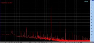
This circuit is my 300B amp driver.
The left (green) is the simulation, the right (red) is the real measuring.
The simulation is close to the real, BUT not match correctly!
The noise level in the simulation FFT totally incorrect, because of the tube model (mathematically) not contains real noise compliances.
Spice tube models -usualy- based on the simple diode model, thus it's noise equivalence is very primitive.
That's why you need to compare your predictions to reality. Those "simple" mathematical functions don't correspond to real pieces of glass and metal. For example, 2.5/gm only works at RF and absolutely ignores the 1/f noise corner. See Blencowe's paper, as well as Vogel's analysis in his book and in his recent Linear Audio paper.
Uh, that is EXACTLY what I just said. Flicker noise, which is also called 1/f noise. It is random and not predictable via mathematical formula. Flicker noise is a function of the cathode material:
"Flicker noise is caused by variations in cathode emission due to movement of atoms within the cathode structure. In oxide-coated cathodes, it occurs primarily at the interface between the oxide layer and the base metal of the cathode, which is generally a nickel alloy. Some alloys are much better than others in this respect, showing a difference of a factor of 20 or more [Smullin59, p65]. A high silicon content increases flicker noise, but unfortunately has advantages in the manufacturing process and so tended to be widely used. The cathode alloy was chosen by each manufacturer, and does not form part of the specification of a particular tube type, which explains the wide variation about tubes from different manufacturers. Smullin [Smullin59] indicates that European manufacturers tended to use alloys which are better in this respect."
Tubes 201 - How Vacuum Tubes Really Work
Therefore, it cannot be modeled and varies from one manufacturer to another.
Perhaps you did not comprehend what I said earlier about spice simulations: They are an indication of RELATIVE circuit performance, not absolute. Simulations are a guide to performance, and are independent of tube manufacturer, so flicker noise is obviously not a consideration.
Also, what papers are you citing? You don't give a title so I don't have a clue what you are referencing. Please provide a complete citation if you expect me to read it. I'm not going to do your work for you. Your citations are so far completely useless.
Last edited:
This circuit is my 300B amp driver.
The left (green) is the simulation, the right (red) is the real measuring.
The simulation is close to the real, BUT not match correctly!
The noise level in the simulation FFT totally incorrect, because of the tube model (mathematically) not contains real noise compliances.
Spice tube models -usually- based on the simple diode model, thus it's noise equivalence is very primitive.
OK, that makes more sense to me now. This is your own design.
I do not know for a fact if thermal noise is modeled in spice. I assume it is. However, flicker noise is dependent on the manufacturing technique and varies a lot and is also random so it cannot be modeled in simulation. You should try tubes from different manufacturers to find one with the least flicker noise.
- Status
- Not open for further replies.
- Home
- Amplifiers
- Tubes / Valves
- Grid Chokes and choke load