Hello guys , I was searching the site for help on how to wire the greyhill switch to a noble pot but the only one that I found was one post by Peter Daniel a long time ago but Am confuse a little bit, here what he said :
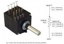
| Here's the drawing of Greyhill switch. To set it for 4 positions, you put the pins as marked: first one goes right above the groove (cut out) in a threaded bushing, the second one defines number of positions and should be inserted after 4 spaces counting from first pin. For 3 positions you place it one hole closer. Put tape over the holes, so pins won't fall out. The tabs should be connected as marked, the separate ones are outputs, the ones in a row counted clockwise from output pins, are inputs. You can choose to switch both signal and ground for both channels independently and than you use both decks and all 4 output pins. An elegant way to do it, is use one deck per channel and upper pins for signal and lower for ground (switching). Use second deck for another channel, but this time use upper pins for ground and lower for signal (switching). This provides some extra isolation between both channels. Best way is to use ohm meter to check connections on a switch. In 4th position (if going by front panel markings) you should be getting Mute, which means input connection on those tabs (on a switch) should be grounded. That effectively grounds the amp's input and provides no signal. |
Attachments
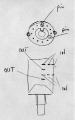
If I Am not mistaken , have to connect signal to every IN position ( 1,2,3 top one ) and ground to every IN position ( 1,2,3 Down one ) and then going to use position 7 to 10 but inverting the connection , signal is goin to be ( 7,8,9 down one ) and ground ( 7,8,9 top one) . I think understood this part, but then I saw this picture and got confused.

Ok, here are my thoughts on the switch connections, because Am going to use one deck per channel, those jumper wires connect ground to pin #4 on one deck and the other one from ground to pin #10. the two wires connected to output pins goes to noble pot but then here is where I get confuse, the other two wires in the background are the input signal (RCA) if they are , how I connect them to the switch ?
Ok guys, I did wire the switch more or less like in the photo, input signal to the top pins at the photo and signal ground to the bottom pins ( pins 1,2,3 ) output pins to ground at noble pot, then at pins 7,8 and 9 connected signal ground to top pins (other side of picture pins 7,8,9 ) and signal to bottom pins ( fto pins 7,8 and 9) and connected 2 wires from ground pins to input on the pot. Then just getting sound from one channel only. Another thing I do not understand is Peter Daniel said is if going to use 3 inputs put the stop pins on pin #1 and pin #4 but how the switch is going to activate pins 7,8 and 9 ? Please guys I need some help.
Think of it as each deck for one channel
So feed signal right 1, 2, 3 into pins 1, 2, 3 of one deck and the output then is taken from their output pin to one deck of the pot.
Feed signal left 1, 2, 3 into pins 1, 2, 3 of the second deck and the output from their output pin to the second deck of the pot.
Grounds most likely don't need to be switched, these can usually be joined together at the input RCA jacks and then fed across the ground pins on the pot. You can of course switch the grounds if you like, but usually its not needed.
So you only end up using input pins 1, 2, 3 out of the 6 possible inputs on that grayhill switch. Use a multimeter to see what connects to what at each switch position. The "stops" just mechanically stop the user moving past position 3, or 4 or whatever.
Thanks woodturner-fran , what I did was feed signal right to 1,2,3 of one deck (top one) and signal ground to 1,2,3 of the other deck ( bottom deck) and then feed signal right to 7,8,9 of one deck (bottom one) and signal ground to 7,8,9 of other deck ( Top deck) but confuse how to connect signal from the switch to the pot ( connected output from the deck of 7,8,9 to input to noble pot, this way only one of the RCA is outputting stereo. Is the way I did switching grounds? But again how you connect signal right and left to the pot? Thanks in advance.
It depends on how many "poles per deck" your switch has. Each deck can have between 1 to 6 poles. See page J-32 of the attached data sheet. You can tell by how poles there are by how many "Common"or output terminals there are on each deck. Each pole is a separate switching section with inputs and one common output. If your switch has two decks but only one pole per deck, you can only switch the R + L signals but not the grounds. You need at least two poles per deck to switch the signals and the grounds.
Attachments
Last edited:
Thanks techtool for reply, It is 2 poles per deck that means I can switch ground, right? The description how I wire the switch is in post #4 but again I confuse how to wire input signal to noble pot, ok here I go, do I have to connect pins 1,2,3 together to one side (input) of pot and pins 7,8,9 together and from here to other input side of pot. Thanks in advance.
Please provide the model number of Noble pot or a photo of the terminals so we know exactly what you have and I will make a wiring diagram for you later today.... still at my day job here.

Sorry techtool, last question , in you diagram you connect pin #2 on noble pot to pole 1 and from there to signal 2 ? same for the output but sorry for a dumb question , then how I activate the other pins, do I also have to connect others pins to wire coming from the pot ? Sorry just trying to understand how the switch works. Thanks in advance.
Well, I assume you are using this for the input to a pre-amp. In this case, signals from the various sources go into the Grayhill switch which functions as the Input Selector Switch. Depending on the switch position, one signal comes out and then goes to the noble pot for volume adjustment and comes out from pin 3 into the rest of the pre-amp. The signal flow is from Left to Right as is common with most electrical drawings. If this is not what you are trying to do, then you will need to give a better functional description of your application. Sorry if I have misunderstood. Don't worry, still willing to help and we will get it.
Ok techtool, first thank you very much to take the time to help me, this is the way I did wire the switch but only one of the input is working in stereo mode, if I disconnect from the working input and connect to the other two only one channel is outputting sound , can leave it like that because Am using my preamp to connect the sources and I still have some empty inputs on the preamp, but if I have to sell my gainclone need to fix these connections problems and what is most important is learn how the switch works. Again thank you, thank you very much, I appreciate your help.Ok guys, I did wire the switch more or less like in the photo, input signal to the top pins( 1,2,3 ) at the photo and signal ground to the bottom pins ( pins 1,2,3 ) output pins to ground at noble pot, then at pins 7,8 and 9 connected signal ground to top pins (other side of picture pins 7,8,9 ) and signal to bottom pins ( to pins 7,8 and 9) and connected 2 wires from ground pins to input on the pot. Then just getting sound from one channel only. Another thing I do not understand is Peter Daniel said is if going to use 3 inputs put the stop pins on pin #1 and pin #4 but how the switch is going to activate pins 7,8 and 9 ? Please guys I need some help.
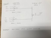
For Deck 1
When the switch is in position 1, the C1 terminal is connected to Pin 1 and the C2 terminal is connected to Pin 7
When the switch is in position 2, the C1 terminal is connected to Pin 2 and the C2 terminal is connected to Pin 8
When the switch is in position 3, the C1 terminal is connected to Pin 3 and the C2 terminal is connected to Pin 9
It is the same for Deck 2
This is assuming your switch has 2 poles per deck and 12 pins per deck and the stop pins are in the right places. I know it can be a bit confusing if your not familiar with these switches. Checking it with a ohm meter or continuity tester is a good way to get a feel for how it works.
- Home
- Amplifiers
- Chip Amps
- Greyhill switch and noble wiring problem