If I may pitch in...
Start with as large as layout as you can....
Identify subcircuits within the schematic and group components to represent this... calculate current in each trace going to V+ and V-. and ground... this will show you wich traces to keep appart...
Then start makeing your layout compact...
But keep even distances between traces... avoid those long diagonal curves... start off only useing right angels (saves time) and at the end mitre corners where suitable...
Try to have adjacent traces have the minimum amount of parallel areas... with the exlusion of traces that are connected by capacitors anyway...
Nordic said:If I may pitch in...
Start with as large as layout as you can....
Identify subcircuits within the schematic and group components to represent this... calculate current in each trace going to V+ and V-. and ground... this will show you wich traces to keep appart...
Then start makeing your layout compact...
But keep even distances between traces... avoid those long diagonal curves... start off only useing right angels (saves time) and at the end mitre corners where suitable...
Try to have adjacent traces have the minimum amount of parallel areas... with the exlusion of traces that are connected by capacitors anyway...
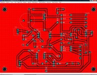
And try to add a powerplane on the copper layer that connects as much unused copper and ground as possible.
That will keep your ground very low impedance.
Attachments
I do not recommend a ground plane as a one size fits all solution...
Once again it needs carefull consideration of what traces are carying what...
One primary downsaide to it is that you are now connecting every singe circiut node to ground with a small capacitor...
Once again it needs carefull consideration of what traces are carying what...
One primary downsaide to it is that you are now connecting every singe circiut node to ground with a small capacitor...
Nordic said:I do not recommend a ground plane as a one size fits all solution...
Once again it needs carefull consideration of what traces are carying what...
One primary downsaide to it is that you are now connecting every singe circiut node to ground with a small capacitor...
Thats only a problem if you have a very small powerplane to trace gap, if it really is a problem at all. I havent found it to be.
If anything the groundplane is screening your circuit from outside noise which sounds good to me.
I would thicken up as much as possible anything taking current and then add the groundplane.
- Status
- Not open for further replies.