There is no valid reason that a well designed PCB can't sound just as good as a well designed PTP version of the same amplifier. The difference is that once the board is properly working, every one will sound exactly the same if the same parts are used in it's assembly. There are plenty of good and bad examples of both construction techniques.
Amen, Brother. I too have been designing all kinds of printed circuit boards since, oh, 1975 or so. Back then, before 'cheap' photoresist, one used stick-on mylar sticky tape to make traces, and equally sticky mylar 'pads' for the drill-thru connections. The trick for 2 sided really was 'drill first, then lay down all the mylar'. Not hard, really. Kind of fun.
Then we got the red mylar film, that stuck nicely to mylar semi-transparent sheets. And photoresist. Suddenly, double-sided wasn't a bear. Kind of more fun, by comparison. And oddly enough, the red-mylar tape-and-dots was “editable”, if after laying out a bunch, you cornered yourself and needed to reroute things. Not a cheap edit, timewise, but still … really not bad.
Etching in big plastic trays of ferric (III) chloride solution, pretty much standard. 15 minutes at 100°F did the trick. Wash, wash, wash, and look in dismay at your stained hands, clothes, shoes, floor, tabletops, notebook, schematic.
That was 1977.
Now one can use an endless number of nearly-free PCB layout tools that include schematic capture, and SPICE simming. Really, we've come a long way. Still … none of the autorouting does a very good job at the outset. It remains better to place components, let auto-routing try to 'solve' it, think about the stupidities it tries, then move components around to try again. When it finally looks pretty good, then manual re-routing takes almost no time, and finishes things off without a hassle.
I've only had one schematic-to-PCB in recent 'times' fail to do what it was wired to do. Further, in the analog domain, it is so easy to enact better-than-decent star grounding, that it just makes me wonder how I used to do it, “back in the not-so-good-old-days”.
Again,
Amen, Brother.
⋅-=≡ GoatGuy ✓ ≡=-⋅
There is no valid reason that a well designed PCB can't sound just as good as a well designed PTP version of the same amplifier. The difference is that once the board is properly working, every one will sound exactly the same if the same parts are used in it's assembly. There are plenty of good and bad examples of both construction techniques.
I have been selling tube amp PCB's for 15 years. Plenty of the amps built 15 years ago are still around, and working fine. Even an inexperienced builder can make a hum free amp because the star grounding system is built into the board at design time.
The reason why I wrote the statement is personal experience and my subjective audition and comparison of PCB based tube audio (therefore: no guitar) amps.
This isn't a scientific forum where for every statement a qualified and objective field study must be double blinded be executed.
We are here to discuss personal experiences and simple basic rules or theories of audio. Much more is impossible with any audio forum on this world.
I have made those experiences with high quality amps that costed me real big money. The first experience was with a Stax tube driver PCB based which I modded by soldering wire onto the layer of copper traces. A unit that was worth 2K Reichsmark three decades ago. Not many people did that abuse. It sure could have been a more cheap gear, but with a Stax electrostatic headphone every detail of change in sound is audible like you use a big magnifier glass.
It brought me very early in my life to this statement that PCB isn't the best thing on earth and has to be avoided when it comes to sound and where it is possible.
Of course, it isn't alsways possible. But when it comes to simple tube amps, almost always it could have been possible to avoid.
Later on I designed my own gear, some of them PCB based.
You may have a complete divergent experience and I'm not talking of measurements in audio. I'm a studied university Telecommunication engineer, so I know what could be measured. But when it comes to the audible sound, I prefer tube amps without PCB very in favor of all others.
Btw, the vast majority of the best and most famous tube amps (including pre) are non PCB gears. Almost all famous studio tubed gear which is called the cream of the worlds best are non PCB based.
Today, they try to copy those gears for studio use but due to the lack of original parts and PCB based CAD this sounds only like a bad copy of the original sound.
I can make a suggestion: play an original Beatles Sgt. Pepper album (the one recorded with the special version of Studer J37 and all tube equipped gear) and make a comparison to any newly recorded LP. If you aren't be able to hear the big differences in favor of the Beatles LP, the equipment is all too bad to make this happen. The Studer had special genes inside and the rest of their employed Abbey Road equipment has them, too. Nothing will ever replicate this sound on earth. And none of their equipment used is PCB based.
P.S. Between "working fine" and "sounding breath taking and top of the best" there is a distance like earth to the moon. And everybody knows that "working fine" is just another term for "just average sounding".
Last edited:
I think there's something quite fun in building a tube amp without a PCB.
A lot of Hi-Fi books introduce the idea of a blameless amp - one which does not impart its own sound. I think I follow that line of thought when building a valve amp. I would think quite differently over a guitar amp where the amp is part of the instrument.
Sadly the valve amps I have built I cannot tell from a modern transistor amp. But that is what I would expect. However they look so much nicer and they glow and have dangerous voltages in them,
The PCB I would imagine is the most blameless part of the amp. If I was going to make a list of things that add colour its would be.
1) Speakers
2) OPT
3) Probably valve non-linearities.
4) Hum
I think you do have to apply some maths to the problem otherwise the earth would still be flat.
On newly recorded music - a lot of modern digital processing (multi band compression for example) takes place to make it 'easy listening' in noisy environments. This reduces the peak to mean ratio and increases the volume and thickens the sound. This tends to reduce the dynamic range so your old LP's may well sound better in a good listening environment. A sign of the times.
Last edited:
baudouin₀;6246575 said:A lot of Hi-Fi books introduce the idea of a blameless amp - one which does not impart its own sound. I think I follow that line of thought when building a valve amp. I would think quite differently over a guitar amp where the amp is part of the instrument.
Yah. There's something to endeavoring to build the most linear and least load-compromised amp, be it FET, BJT, OTL valve, or conventional valve-and-transformer.
The only 3 things so far i've encountered that pleasantly colors the sound emitted by an amplifier are …
№ 1 — high damping speakers and low damping factor amps
№ 2 — Darn good speakers and not-ridiculously linear amps
№ 3 — Old fashioned speakers and “gently” distorting triode amps.
That's about it. My preference, 'cuz I'm old mostly, is № 3. As you've noted, № 2 seems to wash away the differences between amplifier topologies and devices. A big ol' 200 W clean amp of yesteryear does just fine against an assiduously linear valve amp, and they both do surprisingly well against some of the less ghetto Class-D modern amps. But close the eyes, and use a blind-blind ABX switcher and a well adjusted trimpot to ensure exactly the same power output … and it is nearly impossible to hear differences atwixt them. № 1 is a bug, not a feature. Wiggly amps attached to high-damping speakers just seem to develop gremlins. poles-and-zeros in the response curve. Not friendly ones, either. № 2 — Darn good speakers and not-ridiculously linear amps
№ 3 — Old fashioned speakers and “gently” distorting triode amps.
So, again — being old — has caused me to shoot for sweet about-zero-symmetric triode amplification, degenerate cathode resistance biasing, no attempt at GNFB, but plenty of within-the-triode NFB, so that more stages can be used. Contrary to all those years of UCBerkeley Engineering teaching the value of high-and-chosen-to-be-nearly-noiseless front-end amplification followed by a few decent stages thereafter, I tend to like 4 stage amps. Or 5. Not exactly the “more the merrier”, but doing what I can to ensure the nonlinear-but-quite-smooth transfer curves of the combo-of-triodes works out to be very symmetric about the zero crossover.
And it works. Nice 'triode enhancement', without being overly one-sided. And class AB push-pull outputs for somewhat higher efficiency and peak demand power handling.
Ah well… reminiscing.
⋅-=≡ GoatGuy ✓ ≡=-⋅
PC board was invented for several purposes and uniformity of design was the primary design driver. - Tubelab.
That is the true reason behind all automation.
When I came to the Motorola plant in 1973 two way radios were made on assembly lines with rows of workers hand stuffing the same 5 or 6 parts into the board, then passing it down the line. From there they went to End of Line test where they were powered up and basic life tests were performed.
These boards were then transferred to another line where they were hand assembled into their frames and the post switches and other accessories were installed. All customer specific parts like frequency crystals were installed at this point.
From there they to the Final Test Technician. I was one of these techs when I started. We assembled the complete radio, hand tuned every coil and trimmer cap in it to achieve published specifications. The radio went through a set of tests, burn in, then more tests before being boxed up and shipped.
The first handled yield for these products was essentially ZERO. Virtually no radios made the complete trip from board stuffing to product shipment without some repair. Sure, some did, but others needed more than one trip through the loop. An 8 hour shift of several hundred workers produced less than 100 complete radios out the door.
I left the factory tech position for the calibration lab after about a year, and left the cal lab for engineering after 10 years.
When the last manufacturing line in Florida was packed up and sent offshore a crew of about 100 people cranked out several thousand cell phones a day. Reels of SMD parts were placed into a long line and completed, and tested phone boards came out the other end programmed with the carrier information. Another line put these boards into phone housings, and packed them into boxes.
Factory throughput, and therefore cost was the real driver to automation. The quality improvements that it brought was what kept the companies doing it in business. product uniformity is a requirement for both.
The downside....one wrong reel in the process can make a LOT of bad phones before they are caught unless people are paying attention to trends.
I think there's something quite fun in building a tube amp without a PCB
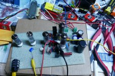
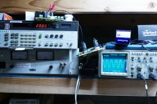
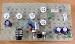
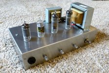
I have built plenty of amps, HiFi and guitar both ways. Many of my projects start out like this, a piece of perf board and a basement full of parts. Stir in some solder and see what comes out. This one will be a guitar amp. It started out as an LT Spice simulation and went on from there. The power amp is built and tweaked to perfection, 20 watts at 3% THD from a pair of 50C5's. (first two pictures)
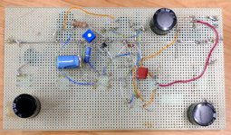
The preamp stages only exist in the computer for now. If I like the complete amp, and may make more than one, I will do a PCB for it. If not it may stay in perf board form forever, or get ripped apart and recycled into something else. You can see by the rosin stains that this piece of perf board has been used before. The previous guitar amp that existed on this board now lives in PC board in a chassis form and has been in that form for about 4 years. (seen on top of the speaker, and ….)
I'm planning a one off vacuum tube guitar amp. It will likely be in PTP or turret board form since I will only build one.
Attachments
-
 P3730055_x.jpg202.3 KB · Views: 110
 -
 P3730057_x.jpg737.3 KB · Views: 105
 -
 NewGuitar_x.jpg862.3 KB · Views: 112
 -
 Amp_0_9_bottom_x.jpg690.6 KB · Views: 101
 -
 Amp_0_9_top_x.jpg635.5 KB · Views: 101
 -
 Chassis_1_x.jpg601 KB · Views: 76
 -
 Chassis_3_x.jpg520.5 KB · Views: 73
 -
 Chassis_4_x.jpg387.8 KB · Views: 81
I have built plenty of amps, HiFi and guitar both ways. Many of my projects start out like this, a piece of perf board and a basement full of parts. Stir in some solder and see what comes out. This one will be a guitar amp. It started out as an LT Spice simulation and went on from there. The power amp is built and tweaked to perfection, 20 watts at 3% THD from a pair of 50C5's. (first two pictures)
The preamp stages only exist in the computer for now. If I like the complete amp, and may make more than one, I will do a PCB for it. If not it may stay in perf board form forever, or get ripped apart and recycled into something else. You can see by the rosin stains that this piece of perf board has been used before. The previous guitar amp that existed on this board now lives in PC board in a chassis form and has been in that form for about 4 years. (seen on top of the speaker, and ….)
I'm planning a one off vacuum tube guitar amp. It will likely be in PTP or turret board form since I will only build one.
Magnificent, actually. I love the perfboard 'breadboarding'. It actually shows “the process” of development.
Your PCBoard is also a classic: hand etched, obviously.
If it were me — I would follow exactly the same steps, except … since I like to 'hack PCBs' with my ancient laser printer and a really hot clothes iron, I'd go about making a one-sided board, and only-as-necessary, on the component side, using zero-Ω wires to 'do what a minimal 2nd side would do'. It works. I used to use carefully trimmed to 8.5 by 11 sheets from the weekly el-cheapo-grocery-store advertisement paper, and print 5× on each sheet. The iron and a big 5 layer pad of aluminum foil transfers the heat quite well, thus melts toner to copper. From there, just soaking in soapy water loosens up the paper; the cheapness of the newsprint is such that with a nylon-type pot scrubber, and gentle circular pressure, I can leave all the resist, and none of the paper.
Wham… into the FeCl₃ it goes. Then acetone (actually Goof-Off) gets rid of the toner. Nice clean boards, too. Plenty fine registration with my old HP laser printer. Now, since the printer died, I just send out to a service to have a board made. I'ven't yet had one fail. $20 or so, and a 2 week turn-around.
Thanks again!
⋅-=≡ GoatGuy ✓ ≡=-⋅