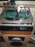
If you're like me, what drew you to the Pearl2 was the adjustable gain in the 'opamp' style 2nd stage. You could adjust the gain to fit the different output levels of cartridges. Unfortunately that's what also kept me from starting!
Dual supply, picking gain resistors, choosing compensation caps, 'instability' ... some people seemed to be having trouble ... 🙁
We'll here's an easy way to get started and have the rest of the circuit working before tackling the 2nd stage. There are no cuts to the PCB and the only 'damage' is the gentle bending (use 2 needlenose!) of 1 outer leg on 1 precious JFET. 😱
The powersupply simplicity of the of the Pearl2 and the 2nd stage simplicity of the Pearl1! Ladies and gentlemen, a hybrid ... the Pearl1.5! 😎
The full board
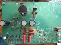
The normal 1st stage
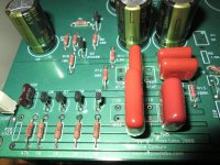
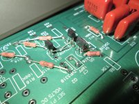
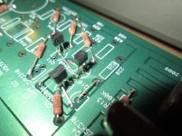
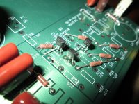
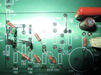
Ah, now the Pearl1.5 second stage!

From a bunch of angles so you can see what's going on:
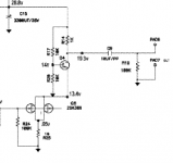
Here's the circuit of the second stage from the Pearl1
View attachment pass pearl1 phono.pdf
Instead of using the unobtainium dual 389FET, I used two 170s in parallel with 10 ohm to gnd like in the 1st stage.
😀

So, from the top you have:
1) 1k going from the bottom of R6 to the top of Q5
2) ztx450 in Q5 (facing the opposite way) with it's top leg going to the top of Q4
3) bridge from the middle of Q4 to the top of R26
4) bridge from the top of C7 to the bottom of C7
5) 10k from the top of Q2 to the bottom of R15
6) 10k from the top of R14 to the bottom of R25
7) 170FET in Q10 (facing the opposite way) with a bridge from the middle of Q10 to the top of R27
8) 170FET in Q11 (facing the opposite way) with its top pin bent to the top of Q10
9) 10ohm from the top of R28 to the bottom of R14
10) 10ohm from the top of R29 to the bottom of R14
11) bridge from top of R17 to bottom of R17
12) regular C8, C13 (output caps! Needed because the output is at half the supply voltage ~ 12V ***note polarity*** silmic2 bypass with Panasonic P polypro) and R18 (output resistor)
Ta Da! It's playing now! I was too excited and I just hooked it up! 😀 (I know, I know unsafe but I ... just ... woohoo!)
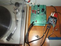
I'll come back and do some measurements but that second stage should be about in the middle of the voltage swing ...
I've been having the time of my life finding little gems in the used vinyl section for $1!
You've got no excuses! Go for it!!!
The Pearl is awesome!
Cheers,
Jeff
Dual supply, picking gain resistors, choosing compensation caps, 'instability' ... some people seemed to be having trouble ... 🙁
We'll here's an easy way to get started and have the rest of the circuit working before tackling the 2nd stage. There are no cuts to the PCB and the only 'damage' is the gentle bending (use 2 needlenose!) of 1 outer leg on 1 precious JFET. 😱
The powersupply simplicity of the of the Pearl2 and the 2nd stage simplicity of the Pearl1! Ladies and gentlemen, a hybrid ... the Pearl1.5! 😎
The full board

The normal 1st stage

Ah, now the Pearl1.5 second stage!

From a bunch of angles so you can see what's going on:


Here's the circuit of the second stage from the Pearl1

View attachment pass pearl1 phono.pdf
Instead of using the unobtainium dual 389FET, I used two 170s in parallel with 10 ohm to gnd like in the 1st stage.
😀

So, from the top you have:
1) 1k going from the bottom of R6 to the top of Q5
2) ztx450 in Q5 (facing the opposite way) with it's top leg going to the top of Q4
3) bridge from the middle of Q4 to the top of R26
4) bridge from the top of C7 to the bottom of C7
5) 10k from the top of Q2 to the bottom of R15
6) 10k from the top of R14 to the bottom of R25
7) 170FET in Q10 (facing the opposite way) with a bridge from the middle of Q10 to the top of R27
8) 170FET in Q11 (facing the opposite way) with its top pin bent to the top of Q10
9) 10ohm from the top of R28 to the bottom of R14
10) 10ohm from the top of R29 to the bottom of R14
11) bridge from top of R17 to bottom of R17
12) regular C8, C13 (output caps! Needed because the output is at half the supply voltage ~ 12V ***note polarity*** silmic2 bypass with Panasonic P polypro) and R18 (output resistor)
Ta Da! It's playing now! I was too excited and I just hooked it up! 😀 (I know, I know unsafe but I ... just ... woohoo!)

I'll come back and do some measurements but that second stage should be about in the middle of the voltage swing ...
I've been having the time of my life finding little gems in the used vinyl section for $1!
You've got no excuses! Go for it!!!
The Pearl is awesome!
Cheers,
Jeff
Last edited:
Yup, everything looks OK. 😉
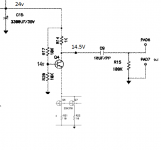
29V in
24V from the regs
14.5V before coupling caps
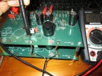
I'm just using a crappy DC walwart and only have 1000uF before the reg and it's still quiet! Man, I love this design! 😀
I'd guess I'm getting about 1Vrms out from my ~5mV Ortofon OM5E(w stylus10).
So ... 1Vrms ~1.5Vpk ... 14.5 + 1.5 = 16V and 14.5 - 1.5 = 13V
So swinging 13V to 16V, I'm well away from the 'rails'. I'm guessing it has about a 1k output impedance judging from the circuit so take that into consideration.
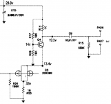
I was driving a 10k pot but just connected about 15cm away. Sounded great!!! Any other considerations?
Do it! I'm talking to you ... ya, you! You know you've been wanting to finally get to it ... and that table is just itching for a new RIAA pre ... DO IT!!1!
😎
29V in
24V from the regs
14.5V before coupling caps

I'm just using a crappy DC walwart and only have 1000uF before the reg and it's still quiet! Man, I love this design! 😀
I'd guess I'm getting about 1Vrms out from my ~5mV Ortofon OM5E(w stylus10).
So ... 1Vrms ~1.5Vpk ... 14.5 + 1.5 = 16V and 14.5 - 1.5 = 13V
So swinging 13V to 16V, I'm well away from the 'rails'. I'm guessing it has about a 1k output impedance judging from the circuit so take that into consideration.

I was driving a 10k pot but just connected about 15cm away. Sounded great!!! Any other considerations?
Do it! I'm talking to you ... ya, you! You know you've been wanting to finally get to it ... and that table is just itching for a new RIAA pre ... DO IT!!1!
😎
Last edited:
Mmmmm, sounds fantastic! Much cleaner in the highs than my commercial op-amp based phonopre.
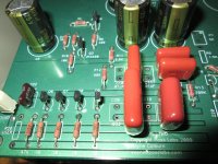
I was able to get exact values of resistors for the riaa section and very close cap values except for the 0.333uF: mine are .335 and .336. I'll get more caps next time I order and get closer on that last match.
I went with the biggest Panasonic FMs (25v, 2700uF, 3.82A ripcur, 14mohm imp, smooth imp curve) for the top 3 final PS filter caps.
47pF silver mica for the cart load. (47k and +~150pF for cabling = ~200pF/47k)
Silmic II in parallel with Panasonic P polypro (non-metalized; like the riaa caps) for output coupling (takes care of the +14.5v from the 2nd stage)
For the Pearl2, Nelson uses Silmic II in parallel with Vishay MKP416, Metallized Polypro ?!?
BFC241641004 Vishay/BC Components | Mouser
Wow, this thing is really Plug-and-Play! Nelson's designs are so robust (and this one, so simple) that basically, if it doesn't burst into flames when you power it up, and a couple of voltages check out ... it's working perfectly!
The Pearl is truly a gem among ... no wait.
Ah-hem, the Pearl shines like a ... Doh!
The Pearl ... sounds great!
Cheers,
Jeff

I was able to get exact values of resistors for the riaa section and very close cap values except for the 0.333uF: mine are .335 and .336. I'll get more caps next time I order and get closer on that last match.
I went with the biggest Panasonic FMs (25v, 2700uF, 3.82A ripcur, 14mohm imp, smooth imp curve) for the top 3 final PS filter caps.
47pF silver mica for the cart load. (47k and +~150pF for cabling = ~200pF/47k)

Silmic II in parallel with Panasonic P polypro (non-metalized; like the riaa caps) for output coupling (takes care of the +14.5v from the 2nd stage)
For the Pearl2, Nelson uses Silmic II in parallel with Vishay MKP416, Metallized Polypro ?!?
BFC241641004 Vishay/BC Components | Mouser
Wow, this thing is really Plug-and-Play! Nelson's designs are so robust (and this one, so simple) that basically, if it doesn't burst into flames when you power it up, and a couple of voltages check out ... it's working perfectly!

The Pearl is truly a gem among ... no wait.
Ah-hem, the Pearl shines like a ... Doh!

The Pearl ... sounds great!
Cheers,
Jeff
Last edited:
Wow, I'm not into audiophool words but the 'sound-stage' is very 'vivid' and 'tight.'
I'm guessing in part to the very close matching in the riaa (except .333uF). My commercial phono must not be as tightly matched.
Here's the full Pearl1.5 schematic:

It's just cobbled together from the Pearl2 pdf (I hope Nelson and Wayne don't mind! 😱 )
And that's pretty much what the circuit is too! A Pearl2 with only the positive power supply and then a Pearl1 2nd stage with 170 instead of 389.
😎
I'm guessing in part to the very close matching in the riaa (except .333uF). My commercial phono must not be as tightly matched.
Here's the full Pearl1.5 schematic:

It's just cobbled together from the Pearl2 pdf (I hope Nelson and Wayne don't mind! 😱 )
And that's pretty much what the circuit is too! A Pearl2 with only the positive power supply and then a Pearl1 2nd stage with 170 instead of 389.
😎
Last edited:
- Status
- Not open for further replies.
