It maybe that doing part of your suggestion Quickshift may work, i.e. binging all the 0V connections together at a single point then feed out to the boards, but keep the RCA and speaker boards connecting to their respective positions on the board. I might have to experiment, though I suspect I am still going to with a dual transformer option in the long run.
Hummmmmmmm
Most people make more out of the hum then is really needed, if it is 60hz hum and I think most of us are familiar with this sound it can only be one thing A GROUND LOOP.
Most people connect there amp board ground to the mains ground this will almost always provide a path for variable resistance in the system even if no other component is earthed.
The boards are well designed and simple both Brians and Peters you dont have to hack traces, the idea behind dual secoundarys is to issolate against 60HZ feed back resistance paths.
1- break the earth ground via 2 diodes a resistor and cap Rod Elliotts site has a simple circuit for this.
2- dont inter connect the center points of both supplys, this will negate all benifits that might be derived from the dual secoudary/ bridge supply. Unless useing only one supply board for both channels.
3- issolate the input grounds from the system grounds, this is the culprit 90% of the time, this is very true if another component is earth grounded, most earth grounded equipment will have a ground lift. lift via a 1 to 3 ohm resistor on the RCA grounds and do not combine channels.
4- Make sure all wireing is neet and away from the trans. and AC power in.😀
Most people make more out of the hum then is really needed, if it is 60hz hum and I think most of us are familiar with this sound it can only be one thing A GROUND LOOP.
Most people connect there amp board ground to the mains ground
this will almost always provide a path for variable resistance in the system even if no other component is earthed.The boards are well designed and simple both Brians and Peters you dont have to hack traces, the idea behind dual secoundarys is to issolate against 60HZ feed back resistance paths.
1- break the earth ground via 2 diodes a resistor and cap Rod Elliotts site has a simple circuit for this.
2- dont inter connect the center points of both supplys, this will negate all benifits that might be derived from the dual secoudary/ bridge supply. Unless useing only one supply board for both channels.
3- issolate the input grounds from the system grounds, this is the culprit 90% of the time, this is very true if another component is earth grounded, most earth grounded equipment will have a ground lift. lift via a 1 to 3 ohm resistor on the RCA grounds and do not combine channels.
4- Make sure all wireing is neet and away from the trans. and AC power in.😀
Hi Ian,
going to two transformer, or quad secondary windings on a single transformer, will allow the two channels to have an independant floating audio ground. Both these floating grounds must be kept separate if you are to avoid an earth loop with connected mains ancilliaries.
However, the floating audio grounds must be made safe and this demands that they are connected to safety earth.
You will need a disconnecting network for each channel to make those safety connections.
An alternative may be Bob Cordell's version using a loop breaking resistor in the RCA return link.
Halo, we have the joys of 50Hz hum here! And it is a big deal when people have spent a lot of time and money trying to solve the problem by all sorts of means and there are relatively simple answers.
I agree with you that the boards are well designed.
There is a loop issue, but it has nothing to do with the safety earth connection, I have tried removing the chassis ground connections to the safety ground for testing purposes and it made no difference (other than stopping a few pops being caused by other appliances in the house, such as the fridge). Also none of my other components have safety earths, so there can't be a loop through the safety earth wiring.
The problem lies with using two rectifier boards with a single transformer that only has 2 sets of secondary windings. As AndrewT has pointed out a quad secondary transformer would be one answer, the second is to use two transformers and the final is to use a single rectifier board. I have yet to try binding the power grounds from the two rectifier boards yet, so can't comment on whether this is a valid solution. It may slightly negate the cross talk benefit of them being separate for the two channels, but you have got twice the current handling and twice the reservoir size by this method.
Hopefully this week or next weekend I can try a couple more configurations.
Andrew, thanks for the tips I'll look up those disconnecting networks and get them installed asap, so that any possible issues with this can be eliminated.
I've had the same problems but haven't got as far as tying discinnecting networks. I'm using dual trafos for the moment, but it would be handy if someone managed to solve the problem for a single trafo, dual PS configuration.
When I finish my main project amps soon, they will be dual PS single trafo but only 1 input channel (active crossover), which I'm hoping won't have the same problem? But maybe I'm being too hopeful.
Stereo or proper dual mono seems to be the safe route to go but 300VA per LM3886 seems extravagant.
When I finish my main project amps soon, they will be dual PS single trafo but only 1 input channel (active crossover), which I'm hoping won't have the same problem? But maybe I'm being too hopeful.
Stereo or proper dual mono seems to be the safe route to go but 300VA per LM3886 seems extravagant.
http://www.diyaudio.com/forums/showthread.php?s=&postid=787773&highlight=#post787773
In post #522 Peter Daniel explains how grounding with a single transformer for 2 channels can be done for a hum-free result.
Klaas
In post #522 Peter Daniel explains how grounding with a single transformer for 2 channels can be done for a hum-free result.
Klaas
Klass,
Good find! Its basically agreeing in part with quickshifts suggestion and one of the ideas I wanted to try.
Jimbo, it would be interesting to know if you suffer from the same problem if you are using an active crossover in the amp case, hopefully if you can keep the paths from the input to the active crossover short you might not have the same problem that we (or is it just me?) are suffering from.
Yes...but in that solution, Peter is basically recommending keeping it to one recitifier board.
What happens when you have two trannies and two rectifier boards? Why would there be a need for an interconnect between the two amp stargrounds?
What happens when you have two trannies and two rectifier boards? Why would there be a need for an interconnect between the two amp stargrounds?
CarlosT said:......What happens when you have two trannies and two rectifier boards? Why would there be a need for an interconnect between the two amp stargrounds?
two floating audio grounds each with their own input RCA and output speaker return terminal are a health hazard.However, the floating audio grounds must be made safe and this demands that they are connected to safety earth.
Both must be made safe by connecting them to safety earth in event of an internal mains fault making these (and other) components "LIVE".
AndrewT:
I know well how you feel about ground earth safety...even if I don't agree 100%.
I thought the focus of this discussion was noise though...
I know well how you feel about ground earth safety...even if I don't agree 100%.
I thought the focus of this discussion was noise though...
Yes, but only if the solutions proposed meet basic safety-requirements.I thought the focus of this discussion was noise though...
Please try to remember there are a lot of readers you are unaware of... we want them all to eventually grow old listening to music 😉
Klaas
hummm
I am trying to think when the last time I bought a amplifier except for commercial, that had the center amp ground connected to the earth, hell they dont even have a 3 prong plug just live and nuetral.
I am trying to think when the last time I bought a amplifier except for commercial, that had the center amp ground connected to the earth, hell they dont even have a 3 prong plug just live and nuetral.
Is it safe to assume a potential reader is aware of the safety-standards that have to be met to safely build a piece of equipment without a connection to safety-earth ?
I dont think so.
Klaas
I dont think so.
Klaas
Hi,
I have said it before and I repeat,
I don't know how to design double insulated (Class11) equipment.
I do know, at least in part, the risks involved in assembling conventional mains operated (Class1) equipment that is necessarily protected by the third earthing pin.
This third pin must effectively keep all exposed conductive parts at a low enough (safe) voltage until the fuse breaks the supply.
CarlosT said:Yes...but in that solution, Peter is basically recommending keeping it to one recitifier board.
What happens when you have two trannies and two rectifier boards? Why would there be a need for an interconnect between the two amp stargrounds?
I think what would happen is that you would connect the chassis ground from each board to the safety earth (as Andrew previously suggested) either directly or via 2 disconnecting networks, one for each channel.
I agree that we need to ensure that the safety of the user is maintained, but I think what we are also saying is that the connection to the safety earth does not form part of the problem, so however it is connected, as long as it IS connected its fine.
AndrewT said:Hi,
I have said it before and I repeat,
I don't know how to design double insulated (Class11) equipment...
AndrewT:
As I stare at the innards of my Adcom GFA535II amp which just has a two-prong plug, I don't see or understand how any of it is "double-insulated."
What is "double-insulated" anyway? Most commercial amp chassis I know of are metal with a metal backplane where all the metal connectors are just mounted to...
When I go to Sears and pick up a "double-insulated" power tool, I see that all I'm touching is made of plastic...no extraneous exposed metal. How could you achieve this in audio amp design? What's the big deal anyway?
If we tried to reduce all exposure to hazzards, we'd just walk around in giant body-sized condoms...that'd take care of disease and electrocution 😀
Hi Carlos,
to reduce our exposure to avoidable hazard, all one has to do is follow the regulations set out to protect us.
Ignore them at your peril.
Why ask me about Class11 devices when I have told you I have no expertise in that field?
to reduce our exposure to avoidable hazard, all one has to do is follow the regulations set out to protect us.
Ignore them at your peril.
Why ask me about Class11 devices when I have told you I have no expertise in that field?
Carlos, I found this which might help:
Class 11, double insulated, is simply the use of two layers of insulation for protection. Internal insulation separates mains conductors from one another, an outer layer of insulation then acts as a barrier to outside contact. For a shock hazard to occur, both layers must be breached.
Class 11, double insulated, is simply the use of two layers of insulation for protection. Internal insulation separates mains conductors from one another, an outer layer of insulation then acts as a barrier to outside contact. For a shock hazard to occur, both layers must be breached.
Sorry to chime in, but I was directed here by chance.
Isn't it Roman numbers?! Like Class I and Class II as in Class 1 and Class 2? Note that this question is rhetorical! 😀
I didn't follow the thread but the difference between those two classes is actually straight forward.
In Class 1 equipment, every conductive (i.e. metal) part that could possibly maybe be touched by a user (i.e. enclosure and connectors) has to be connected to mains protective earth (PE), the green-yellow wire that someplace has a different color but the same purpose. 😀
In Class 2 equipment, all mains related circuitry has to have double insulation between life or neutral and anything else in the unit, even internal circuitry right next to the mains wiring. Double insulation is achieved both through creepage (physical distance) and coverage (appropriate materials wrapped around).
Class 1 is achievable for the DIY enthusiast. That's why every project site recommends it. If your unit fails, it fails safe - unless you skimped on the PE wiring.
Class 2 requires every single component that has to do with the mains (primary) side to be certified for class 2 usage by regulation and safety authorities. Compliant wire, compliant board connectors, compliant board layout techniques, compliant transformer, etc. That's why no DIY project site recommends it. It's only reasonable for someone who has training and/or experience in that field.
Rest assured that a DIY product of the average hobbyist would fail the first couple of times of UL, IEC or VDE testing in a jiffy. That's why nobody tries: You are responsible for what you switch on and leave running. And when your house burns down or someone dies, you're still responsible.
In short: we want our amplifiers and sources to be class I (one) devices, because we can. If it gives us headaches because we mess up the ground layout, we improve upon it. If we get into the realm of multiple homegrown class I devices humming together to no avail, we convert to balannced interconnects! 😀
Should we at some point feel the need to mess with class II (two) equipment, we first make shure we know exactly what serves which purpose - and we replace broken parts with certified and approved parts only.
You're dead if you do it wrong. If you do it wrong and survive out of luck, it'll be your kids who die. Or your kitty... You get my point, Carlos! It's not funny.
Read up on it , it's not too difficult to learn.
Cheers,
Sebastian.
Isn't it Roman numbers?! Like Class I and Class II as in Class 1 and Class 2? Note that this question is rhetorical! 😀
I didn't follow the thread but the difference between those two classes is actually straight forward.
In Class 1 equipment, every conductive (i.e. metal) part that could possibly maybe be touched by a user (i.e. enclosure and connectors) has to be connected to mains protective earth (PE), the green-yellow wire that someplace has a different color but the same purpose. 😀
In Class 2 equipment, all mains related circuitry has to have double insulation between life or neutral and anything else in the unit, even internal circuitry right next to the mains wiring. Double insulation is achieved both through creepage (physical distance) and coverage (appropriate materials wrapped around).
Class 1 is achievable for the DIY enthusiast. That's why every project site recommends it. If your unit fails, it fails safe - unless you skimped on the PE wiring.
Class 2 requires every single component that has to do with the mains (primary) side to be certified for class 2 usage by regulation and safety authorities. Compliant wire, compliant board connectors, compliant board layout techniques, compliant transformer, etc. That's why no DIY project site recommends it. It's only reasonable for someone who has training and/or experience in that field.
Rest assured that a DIY product of the average hobbyist would fail the first couple of times of UL, IEC or VDE testing in a jiffy. That's why nobody tries: You are responsible for what you switch on and leave running. And when your house burns down or someone dies, you're still responsible.
In short: we want our amplifiers and sources to be class I (one) devices, because we can. If it gives us headaches because we mess up the ground layout, we improve upon it. If we get into the realm of multiple homegrown class I devices humming together to no avail, we convert to balannced interconnects! 😀
Should we at some point feel the need to mess with class II (two) equipment, we first make shure we know exactly what serves which purpose - and we replace broken parts with certified and approved parts only.
What's the big deal anyway?
You're dead if you do it wrong. If you do it wrong and survive out of luck, it'll be your kids who die. Or your kitty... You get my point, Carlos! It's not funny.
I don't see or understand how any of it is "double-insulated.
Read up on it , it's not too difficult to learn.
Cheers,
Sebastian.
Andrew,
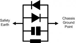
Just looking through at your suggestions for a disconnecting network, they are one or more of the following:
10r power resistor.
power bridge diode wired in inverse parallel.
high frequency capacitor (10nF to 100nF ceramic).
Can you just give me a little clarification, would you class a power resistor as 2W or more?
A power bridge diode as handling how many amps?
I would assume the arrangement is as shown in the attached diagram.
Attachments
- Status
- Not open for further replies.
- Home
- Amplifiers
- Chip Amps
- Got Chipamp Hum? Possible Solution