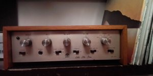
It is an AM-320 from palace audio, it only had a broken powersuply cap. So when I replaced it I was like: "Wow that was easy" but noo!
I mean, it does work now. But the noise floor is terrible (like 50% signal 50% noise)...
I was wondering if I could get some guidance for where to look next... Maybe the potentiometers make bad contact or the transistors grew to old and need replacement??
I would love to get it running, it would be my first "old vintagy" amp.
However, making a full repair (replacing every cap, etc) wouldnt appeal much to me lol...
Here are some photos: (The transistors are: AD162 and 25B474)
Attachments

Last edited:
What is "noise"? Hiss? Humm? Crackle? Static? Lawnmower? Motorboat? Steven King Radio?
And what does or does-not change the noise? Volume? Bass, treb, balance? Tape, phono? A good shake?
The amp is old and as you can see by the double-stamping made as cheap as possible. So almost anything can be bad.
And what does or does-not change the noise? Volume? Bass, treb, balance? Tape, phono? A good shake?
The amp is old and as you can see by the double-stamping made as cheap as possible. So almost anything can be bad.
Could be oscillating, for example. Major problems in old amps is not unusual.
Insert shorting plugs in all inputs, and see if the noise goes away.
Insert shorting plugs in all inputs, and see if the noise goes away.
Never heard of the brand but I knew I had seen that series of amplifiers.palace audio
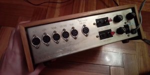
99% sure it was made by Itoka, Tokyo, Japan. For foreign sales-- tell them what knobs and logo you wanted, how many, they'd make it. This or a similar factory did a lot of work for US Radio Shack. Palace and also Sound Sonics in Australia.
From the pictures I can see mixed power transistors. AD mixed with 2SA types. Perhaps they don't like each other. Find out what the originals were.
{as MAACO's sharp eye spotted:} The later is 2SB474.transistors are: AD162 and 25B474
The 2SB is PNP Germanium; the AD is NPN Silicon. In 1969 it was common to find a mixed-pair like this. PNP Ge was cheaper, but a NPN is a great convenience and usually Si.
There's no particular problem because the designer knew about the two types.
Not Correct.{as MAACO's sharp eye spotted:} The later is 2SB474.
The 2SB is PNP Germanium; the AD is NPN Silicon. In 1969 it was common to find a mixed-pair like this. PNP Ge was cheaper, but a NPN is a great convenience and usually Si.
There's no particular problem because the designer knew about the two types.
The old AD (161/162) were Germanium driver transistors. Sometimes used as low power outputs in amps
with no more than 5 watt output. More like 3 watts. Since there´s only 162, this amp has single supply and big (2200-4700) electrolytic in output.
The more powerful TO-3 version of that time was AD-149.
Since this probably is a pure germanium all through, the "hiss" is far worse than in a silicium/silicon ditto.
It´s just, the way it is 🙂
https://www.web-bcs.com/transistor/tc/ad/AD162.php
https://www.web-bcs.com/transistor/tc/ad/AD161_cpl.php
Last edited:

Dried up electrolytic caps can cause hum, or too much highs or lows in couplers and filters. They don't cause hiss or gravel. Tiny dried up electrolyics in the radio part can detune the discriminator & make performance terrible. I use 50 v ceramic disk caps for these .47 uf or 1 uf caps. I re-e-capped a 1978 radio, made the FM section perform great and no alignment required. Film dielectric (mkp) caps past ~1968 don't deteriorate. SCR brand film caps became notorious. (FR) Ceramic disk caps deteriorate only if the metal is exposed to the air. (common in cheapo ceramic caps into the nineties).But the noise floor is terrible (like 50% signal 50% noise)...
I was wondering if I could get some guidance for where to look next... Maybe the potentiometers make bad contact or the transistors grew to old and need replacement??
However, making a full repair (replacing every cap, etc) wouldnt appeal much to me lol...
Sixties transistors of either substrate can cause itermittant popping from surface contamination. *****y design can cause hiss in radio sections. I never had a Germanium appliance except radios, and those were really insensitive and tended to wander off station badly. Cheapo design. Quality radio design in 1966 like Grundig Philco GE stayed with vacuum tubes.
Bad connections can cause distortion, donald duck talk. Unplug & replug, maybe wash with 70% alcohol. Bad connections can include bad solder joints and high resistance potentiometer wipers.
Sixties resistors can cause hiss, especially those 100 kohms & higher. Replace with metal film resistors of same value. Up the wattage, modern metal film resistors are watt rated at 200 deg C or so which will burn a PC board. (Vishay started this). Use same physical size resistor (3* to 10* watts) or look for 300 v higher rated resistors if can't get dimensions.
Last edited:
A mix of everythingWhat is "noise"? Hiss? Humm? Crackle? Static? Lawnmower? Motorboat? Steven King Radio?
It sounds like a rainy beach or a waterfall
Noise of the aux in:
https://drive.google.com/file/d/1shIefIDQrlN9YA5C3c3h2nIoKKjUiOMc/view?usp=sharing
The noise changes depending of the input (i plan to use mainly the AUX in to use it with other equipment). The vol knob only has a little hiss when it is on maximum (but does not amplify the "other"? noise).And what does or does-not change the noise? Volume? Bass, treb, balance? Tape, phono? A good shake?
The bass and treb controls changes the noise tone.
The sound does not change when shaking it
This "waterfall" noise suggests that one or more voltage amplifier transistors in the audio section may be defective. I've often found this fault on early '70 Pioneer amplifiers, The transistors may become noisy. High value resistors do sometimes becomes noisy too.
Some resistors are probably out of spec and have gone noisy. I’d look at them before any transistors. Transistors tend to either work or not work at all. I’ve had a bad resistor cause measurably higher distortion in one channel compared to the other. That was a fun one to track down.
Do you hear the noise in both channels or just one? What happens when you short the inputs?
Do you hear the noise in both channels or just one? What happens when you short the inputs?
Hmm Tomorrow I will test the circuit stages separately and see what happens...
...
The audio I sent was recorded directly from the output, the noise is different in each channel.Do you hear the noise in both channels or just one? What happens when you short the inputs?
...
A mess:
Looking at It gave me headaches... It's all mixed up lol
But I could recognize some things:
All the inputs go to the selector and then enter the vertical PCBs that have riaa and preamplification depending on the input type.
The output of that goes to the vol pot (it attenuates) and then to the balance and the tone controls
Then it enters the main PCBs (I didn't unscrew those because I was worried to break them).
Probably the noise comes from these...
Attachments
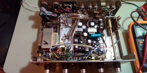
Looks pretty messy but the component count doesn't seem too bad. The output transistors are probably transformer coupled judging by the looks of things. But why one is mounted different than the other? If you're serious about keeping it then I would replace all the electrolytic caps and most of the resistors. Unfortunately there doesn't seem to be a schematic available.
I think they didn't had enough components when building it and used equivalents, or maybe someone replaced them before me...But why one is mounted different than the other?
Hmmm or maybe I could scrap it and use the transformers and the enclosure for something else (I really like how robust it looks). Or sell it. But I'll keep it for now...If you're serious about keeping it then I would replace all the electrolytic caps and most of the resistors.
- Home
- Amplifiers
- Solid State
- Got an old broken receiver from the 60s, repaired it but the noise floor is still to high.