Test the primary only, if you measure from the secondary you generate lethal voltages in the primary (so be careful), and see the substantial stray capacitance of the primary transformed to a much larger capacitance viewed from the secondary (in fact the secondary can look capacitive with an unloaded primary even at fairly low frequencies).
Looking from the primary sees only tiny reflected capacitance from the secondary, and its own unmagnified capacitance which won't dominate till much higher frequencies.
Naturally, safety comes first... leads were clipped and secured. I intended to measure capacitance from the primary, but good information nonetheless.
Now I am having a new and rather interesting problem... When trying to measure the primary inductance directly, the current is so low that I cannot reliably measure the voltage across the 10 ohm sense resistor due to noise radiating from the test circuit. Even moving the probe around the test point is inducing millivolts.
Last edited:
White paper on extracting transformer values:
https://www.omicron-lab.com/fileadm...ling/App_Note_Transformer_modelling_V_2_0.pdf
https://www.omicron-lab.com/fileadm...ling/App_Note_Transformer_modelling_V_2_0.pdf
I'd refrain from using mains for any testing like this, signal generator, multimeter. A signal generator will give a single frequency at a time, so you'll be able to see the response of the device under test without the confounding influence of unknown mains waveform and a variac's response and possible saturation of the core.
The primary, being high impedance, shouldn't be loading the siggen very much either.
The primary, being high impedance, shouldn't be loading the siggen very much either.
I'd refrain from using mains for any testing like this, signal generator, multimeter. A signal generator will give a single frequency at a time, so you'll be able to see the response of the device under test without the confounding influence of unknown mains waveform and a variac's response and possible saturation of the core.
The primary, being high impedance, shouldn't be loading the siggen very much either.
Point taken
What voltmeter do you have?
A modern cheap multimeter that measures true rms will average to help reject noise, and a meter with a millivolt range is practical in this test situation.
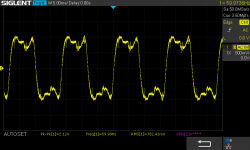
A scope with a grounding wire can pick up noise from the ground wire 'loop', so you may benefit from using a stub type ground clip to measure the voltage across a resistor. A scope also may have a poorer method of measuring rms level. But if your waveform is valid, then there is an issue with either the test setup or with the transformer, as that waveform is not consistent with a typical magnetising current waveform of a power transformer primary winding, where there is no loading on any winding.
A modern cheap multimeter that measures true rms will average to help reject noise, and a meter with a millivolt range is practical in this test situation.
A scope with a grounding wire can pick up noise from the ground wire 'loop', so you may benefit from using a stub type ground clip to measure the voltage across a resistor. A scope also may have a poorer method of measuring rms level. But if your waveform is valid, then there is an issue with either the test setup or with the transformer, as that waveform is not consistent with a typical magnetising current waveform of a power transformer primary winding, where there is no loading on any winding.
Last edited:
I believe I have some tangible results. Firstly I would like to confess the my mind was in RMS when I really wanted peak to peak for the primary. I am rather embarrassed by such a rookie mistake. The transformer begins to saturate at 252Vpp at 20Hz. The results are taken at 240Vpp across the winding...
20Hz 225H
30Hz 160H
40Hz 129H
50Hz 107H
60Hz 93.76H
70Hz 83.87H
These numbers seem much more in line with what I was expecting.
20Hz 225H
30Hz 160H
40Hz 129H
50Hz 107H
60Hz 93.76H
70Hz 83.87H
These numbers seem much more in line with what I was expecting.
Results look goofy, where are you getting 240v pp to drive primary and how are you measuring current? What are current and voltage at ea h frequency?
Voltage was generated by my laptop then amplified by a 4p1l driven 6p36s capacitor coupled to the primary. Current was measured by a 10 ohm sense resistor in series with the winding and measured using a Fluke 115 true RMS multimeter. Driving voltage was monitored for consistent 240Vpp with an oscilloscope.
Current measurements are as follows:
20Hz 3mA
30Hz 2.8mA
40Hz 2.6mA
50Hz 2.5mA
60Hz 2.4mA
70Hz 2.3ma
Current measurements are as follows:
20Hz 3mA
30Hz 2.8mA
40Hz 2.6mA
50Hz 2.5mA
60Hz 2.4mA
70Hz 2.3ma
You won't get useful results that close to saturation due to excitation current, try 10x less voltage. If current is RMS voltage should also be. Be sure to monitor voltage after coupling cap and that sine is not distorted.
The intended application wouldn't be very useful at 10x less voltage. The transformer is used as an output transformer for a tube amp. The inductance was calculated at 84.85Vrms as the current was measured in rms. I couldn't tell you the THD figures, but given the inherent distorted nature of a SET amplifier, I would say these results are pretty "real world" and more applicable to the task at hand.
20Hz 225H
70Hz 83.87H
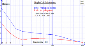
Can someone please explain inductance to me in simple terms? - Page 2
This is a pickup, not a closed core; but the 20-70Hz trend parallels yours. About 3:1 change of L.
Attachments
If you only have a Fluke 115 then yes any measurements with that will get a bit suspect if voltage is below about 10mV due to accuracy (given you were measuring 23-30mVrms levels), but also would be of concern if the distortion level was substantial, even though the 115 has a frequency range out to 0.5-1kHz.
Your Siglent scope may provide better accuracy if you want to reduce the excitation voltage, but still use an insignificant current sense resistance (10 ohm compared to primary winding ESR of 50 ohm). You could cross-compare at the 240Vpp level with the Fluke.
When presenting results on a forum, many of us happily relate to measurements made using a sinewave for excitation (eg. within a % or 2 of distortion), and at low rms voltage of 5 to 20V, and at a standard mains frequency. That then allows comparison with how other output transformers are typically specified.
That seemingly low test voltage level (5-20Vrms) is also useful for stability assessment for those amplifiers with global feedback - again due to comparison with other amps and their OT's.
The concern is that if results are presented using a very distorted excitation waveform, then there is some doubt as to whether the test setup/measurement has some gremlin in it, or whether there is any useful information in the measurement results (apart from knowing the transformer doesn't have a fault, and has sufficient inductance to keep magnetising current at an acceptable level at the rated mains AC voltage and frequency - ie. the primary purpose of a power transformer).
I will measure again at a lower voltage this evening. The lower voltage means I can remove a gain stage, and with that I can use a lower distortion signal. I was having trouble measuring current at 20Vrms yesterday, even with the scope, before I had to stop testing.
For the life of me I cannot get a current reading at 20Vrms no matter the source driving the transformer. I am getting too much noise across the sense resistor. I am going to try and sort out the noise problem. But that may take some time.
Multimeter in ac current mode in series with winding, should be reliable.
I stopped buying $30 multimeter fuses years ago... hahahahaha, so no dice on that route. Anyways, I ended up trusting Ohm's Law, and popped in a 10K resistor in series with the winding to get above the noise floor, instead of fighting it. Take these results as you may...
20 Hz 612H
30Hz 461H
40Hz 331H
50Hz 254H
60Hz 244H
These were gathered at 20Vrms
Burning multimeter fuses is normally a result of leaving them on a current setting rather than voltage. I don't think I've blown a meter fuse more than once or twice, I learnt the lesson.
- Home
- Design & Build
- Parts
- Goofy transformer measurements