Hello all
What do you think about this amplifier?
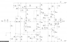
The performance it seems to be very good. Distorsion levels for second and third harmonics will be down into five-digit region at 1kHz and two-pole compensation pushes distorsion at 50kHz down to 0.0014% for second harmonics and 0.00052% for third harmonics.
Overal THD is approximately 0.0009%.
P = 80W rms, 8ohm
I don't know who is the designer of this hifi amp...
What do you think about this amplifier?
The performance it seems to be very good. Distorsion levels for second and third harmonics will be down into five-digit region at 1kHz and two-pole compensation pushes distorsion at 50kHz down to 0.0014% for second harmonics and 0.00052% for third harmonics.
Overal THD is approximately 0.0009%.
P = 80W rms, 8ohm
I don't know who is the designer of this hifi amp...
Attachments
bogdan_borko said:Slone I think.
BTW I never belived his thd figures...
O yes, my vote is for R Slone too.
Is there anybody who buid it?
I read some parts of his book and I`m NOT impressed at all... and somebody from the forum had trouble making one of his designs. Fairly complex for nothing, i think.
roender said:Hello all
What do you think about this amplifier?
The performance it seems to be very good. Distorsion levels for second and third harmonics will be down into five-digit region at 1kHz and two-pole compensation pushes distorsion at 50kHz down to 0.0014% for second harmonics and 0.00052% for third harmonics.
Overal THD is approximately 0.0009%.
P = 80W rms, 8ohm
I don't know who is the designer of this hifi amp...
Very professional design of a standard op-amp type, one of the best I've seen here. Built with low distortions in mind, also well protected against damage because of output overcurrent.
May sound perfect if you have a lot of headroom, when overdriven will ruin the sound.
Okay, i checked the amp closely in sims...
THD values are impressive, BUT...
1khz 1w into 8ohm = 0.001% THD
1khz 50w into 8ohm = 0.0005% THD
10khz 1w into 8ohm = 0.0007% THD
10khz 50w into 8ohm = 0.001% THD
20khz 1w into 8ohm = 0.007% THD
20khz 10w into 8ohm = 0.016% THD
20khz 50w into 8ohm = 0.0095% THD
symasym:
1khz 1w into 8ohm = 0.0008% THD
20khz 1w into 8ohm = 0.001% THD
20khz 10w into 8ohm = 0.004% THD
20khz 50w into 8ohm = 0.011% THD
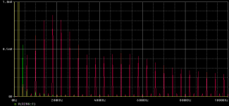
At 20khz this design fails in a way that is simply disgusting. Its very likely that this is the typical amp measuring exceptional, but sound like broken glass.
Attached is FFT-plot from sims for 20khz 10w into 8ohms, red is your showed design, green/yellow is symasym at same powerlevel. (I guess no comment is necessary)
I believe that an amp sounds like it weakest point, most standard designs completely fail at high frequencies.
Possibly that circuit might sound good if biased into ClassA. I guess this amp suffers from its CFP-output.
Mike
BTW, i never trust a circuit that reduces THD with increased power levels...
THD values are impressive, BUT...
1khz 1w into 8ohm = 0.001% THD
1khz 50w into 8ohm = 0.0005% THD
10khz 1w into 8ohm = 0.0007% THD
10khz 50w into 8ohm = 0.001% THD
20khz 1w into 8ohm = 0.007% THD
20khz 10w into 8ohm = 0.016% THD
20khz 50w into 8ohm = 0.0095% THD
symasym:
1khz 1w into 8ohm = 0.0008% THD
20khz 1w into 8ohm = 0.001% THD
20khz 10w into 8ohm = 0.004% THD
20khz 50w into 8ohm = 0.011% THD
At 20khz this design fails in a way that is simply disgusting. Its very likely that this is the typical amp measuring exceptional, but sound like broken glass.
Attached is FFT-plot from sims for 20khz 10w into 8ohms, red is your showed design, green/yellow is symasym at same powerlevel. (I guess no comment is necessary)
I believe that an amp sounds like it weakest point, most standard designs completely fail at high frequencies.
Possibly that circuit might sound good if biased into ClassA. I guess this amp suffers from its CFP-output.
Mike
BTW, i never trust a circuit that reduces THD with increased power levels...
Attachments
it is a slone design.
probably a decent performer, certainly not the best there is.
others have built this design and been happy with it.
his distortion numbers are simulations, so beleive at your own risk. 😉
the previously referred to problem was with a different design, not this one. that problem was when using current mirrors with a complementary symmetrical design, some voltages were undefined. i beleive it was stated that slone agreed with this assessment after questioned about it. more details can be found via the search function.
good luck and have fun!
mlloyd1
MikeB:
"At 20khz this design fails in a way that is simply disgusting. Its very likely that this is the typical amp measuring exceptional, but sound like broken glass."
Outrageous...especially the 9th harmonic with powerful 92 nW!
Mike, you must have good speakers and ears...😉
Heinz!
"At 20khz this design fails in a way that is simply disgusting. Its very likely that this is the typical amp measuring exceptional, but sound like broken glass."
Outrageous...especially the 9th harmonic with powerful 92 nW!
Mike, you must have good speakers and ears...😉
Heinz!
This is a Slone' design. He used to use D669 🙂
Another his design is Symytrical amplifier with current mirror .
There are so many man who say " this design only run on Sim".
Are there anyman which build this design( symytrical..) ?
Another his design is Symytrical amplifier with current mirror .
There are so many man who say " this design only run on Sim".
Are there anyman which build this design( symytrical..) ?
powerbecker said:
Outrageous...especially the 9th harmonic with powerful 92 nW!
Mike, you must have good speakers and ears...😉
Heinz!
From what i learned/experienced, this amount of high order harmonics makes the sound unpleasant/bright to the ear.
Anyway, if you sum up all these harmonics, the energy from these will be much higher than 92nW ! 😉
I got much better sounding amps when i started to care about these.
Mike
Mike:
"Anyway, if you sum up all these harmonics, the energy from these will be much higher than 92nW ! "
of course... but the frequency is also much higher... 😉
"I got much better sounding amps when i started to care about these."
One reason more to love my tinnitus : So I have not to care about those low level sound pressure 😀
BTW: So far I remember it´s impossible to hear down to 20 phon, because there is a lot of "noise" in the "background", one of it come the streaming blood, and another one is the ground wave!!
But in prinzip I´ll agree (depends of level and frequency)!
Heinz!
Dual-slope roll-off was mentioned by Self. THe rest of the amp. is almost the same as his "blameless" except for using complementary feedback pairs in the output.
At high frequencies the 2-pole roll-off resistor loads the VAS, so I recommend increasing the current or this stage could overload at high frequencies. Also, there is typically a peak in the frequency response curve around the point where the 2-pole roll-over changes to single.
And at high frequencies the 2-pole slows the amp. down just as a single. But distortion levels are of course improved...
Another point is that why do people add resistors like R14 (I think this is the one - diagram not too clear) in series with the base of the current source? This adds noise, causes the current source to have a reduced frequency response through capacitive (Ccb) coupling. Why not short it out? Self tended to add these for no apparently good reason.
Reckon with a few improvements this could be a better amp.
John.
What is the significance of the input caps? The only reason that I can think of is that maybe polarized caps are nonlinear and can cause 2nd harmonics, so this arrangement cancels out 2nd harmonics. But wouldn't this create 3rd harmonics? Or does the decrease in capacitance lower the current and put the caps at a more tolerable level?
Just wondering.
keantoken
Just wondering.
keantoken
john_ellis said:
Another point is that why do people add resistors like R14 (I think this is the one - diagram not too clear) in series with the base of the current source? This adds noise, causes the current source to have a reduced frequency response through capacitive (Ccb) coupling. Why not short it out? Self tended to add these for no apparently good reason.
John.
The initial reason could be to limit base current when the transistor is saturated. Somewhere sometimes it is a good reason.
Wavebourn said:
The initial reason could be to limit base current when the transistor is saturated. Somewhere sometimes it is a good reason.
Maybe. A better way to prevent saturation is to use anti-sat clamping diodes. But I've not seen a problem with saturation in a current source if the base current is limited (for example if fed by a moderately low current and pair of diodes etc). Anti-sat diodes added to a VAS really speeds recovery from clipping up.
John
- Status
- Not open for further replies.
- Home
- Amplifiers
- Solid State
- Good old schematics