Gordy said:richwalters, thanks for the very interesting pointer. However I can't find that transformer (9818, 3:1) on the Sowter site, so is it a special and could any other (Sowter or otherwise) be effectively substituted in?
Another professional audio story shortened. Originally the application was for an octave shifter o/p but I was so pleased with its performance that it ended up in a balanced o/p preamp...
The original design I was after, was the transformer to be wound on a toroid core customed to one of my horrific (put off) specifications of exactly how it should be wound. There is no tube type commercial equivalent which offered a suitable spec. There are some winding houses still around but I've lost contact with the famous who used to do mixed mu/iron metal prototypes. The nearest type is the Sowter 8940 cathode follower to 600 ohm line transformer which I got them to modify to the 9818 version. Technically this version is an upped inductance version (50H) to handle lower frequencies without running into distortion. So the winding has more sections and is more pricy.
Avoiding dBm or u's for the moment, the output circuit (as expected) easily cranks 3V rms o/p at 0.06% thd at 30Hz; 0.035% at 1K and 10Khz into 600ohms this corresponds to 9V on the cathode follower o/p this is very good. . If lower levels are required then the 8940 will do for your app. SY does a good circuit example. So that's why I'm using an elevated B+ of 225V. Also the heaters need to be separated and elevated from rest of circuitry.
Sowter doesn't wind toroids. So I got them to wind a conventional on an E&I core with part mu metal and SiFe. Looking at the circuit signal/noise ratio,which in my case = around -95dBu the E&I transformer has to kept well away from other magnetic sources in the chassis. The cathode follower has a noise floor well lower than -95dB and ANY AC mag field will get picked up.
If a volume control is fitted on the input circuit to the drawing I provided, then choose a value lower enough not to slew squarewave in mid travel. Alot of variables can be done but depends on how much the preceding stage can be loaded.
A toroid design would offer better space utilisation without fear of ext signals. -90 down is a very low noise level.
Although my main amp has an inp Z of 1500 Ohms, no added snubbers were necessary.
:-rj
Gordy,
some more digression.
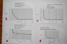
Some discovered graphs of the ECC88 cathode follower which I previously described; for illustration only,
Graph A; Shows the typical performance into a 600 Ohm load at elevated output voltage of 17dBu.This is a voltage excursion way beyond all main amplifier input levels. As expected the parafeed transformer BH curve swing increases with lower f thd.
Graph B; The cathode follower with parafeed transformer in trouble: Low frequency thd combined with decreasing output load impedances aren’t ideal conditions. In certain studio applications the increase of iron 2nd harmonic enhances "the dummy bass" in small HiFi systems with poor acoustic LF response.
Graph C; The typical 0dBu “normal” application performance into 600 Ohm load. Despite the thd rise at the lower f end due to increasing tranny BH curve, is very acceptable. Overall mid range thd is very low.
Graph D; Cathode follower at elevated output voltage of 17dBu driving virtual infinite 10K input Z. Again a level unlikely to be encounted.
THD in this design which used pentodes strapped as triodes, comprises entirely of 2nd harmonic.
In graphs A & D the output voltage corresponds to approx 17V rms on the cathode follower cathodes which is nearly 50VAC p-p. If one wants the headroom then the volts is required.
The 0.04% thd enamates mainly from the remaining preamp circuitry and transformer.
The 9818 HF droop begins -1dB at 36Khz;-3dB at 62Khz and at 0dBu -0.5dB at 6Hz.
If you want a lower ratio parafeed then by all means fine but circuit noise levels will increase. With a high preamp B+ it's better to design with high signal levels hence a good overhead margin. Having gone about this the easy way, the crème is to fit a feedback winding and to develop the circuit into a wider b/w p-p parafeed. By doing this, the output Z is even lower.
Compromises are everywhere.
Having gone about this in the recording industry levels i.e capable of a +20dB headroom above 0dBu, it's quite clear that for normal HiFi such voltage levels aren't required.
The Sowter 8940 quotes 0.5% thd at 50Hz at. At 20Hz it will be appreciably higher. Worth a try if you are around the 0-3dBu level.
Happy designing !
richj
some more digression.
Some discovered graphs of the ECC88 cathode follower which I previously described; for illustration only,
Graph A; Shows the typical performance into a 600 Ohm load at elevated output voltage of 17dBu.This is a voltage excursion way beyond all main amplifier input levels. As expected the parafeed transformer BH curve swing increases with lower f thd.
Graph B; The cathode follower with parafeed transformer in trouble: Low frequency thd combined with decreasing output load impedances aren’t ideal conditions. In certain studio applications the increase of iron 2nd harmonic enhances "the dummy bass" in small HiFi systems with poor acoustic LF response.
Graph C; The typical 0dBu “normal” application performance into 600 Ohm load. Despite the thd rise at the lower f end due to increasing tranny BH curve, is very acceptable. Overall mid range thd is very low.
Graph D; Cathode follower at elevated output voltage of 17dBu driving virtual infinite 10K input Z. Again a level unlikely to be encounted.
THD in this design which used pentodes strapped as triodes, comprises entirely of 2nd harmonic.
In graphs A & D the output voltage corresponds to approx 17V rms on the cathode follower cathodes which is nearly 50VAC p-p. If one wants the headroom then the volts is required.
The 0.04% thd enamates mainly from the remaining preamp circuitry and transformer.
The 9818 HF droop begins -1dB at 36Khz;-3dB at 62Khz and at 0dBu -0.5dB at 6Hz.
If you want a lower ratio parafeed then by all means fine but circuit noise levels will increase. With a high preamp B+ it's better to design with high signal levels hence a good overhead margin. Having gone about this the easy way, the crème is to fit a feedback winding and to develop the circuit into a wider b/w p-p parafeed. By doing this, the output Z is even lower.
Compromises are everywhere.
Having gone about this in the recording industry levels i.e capable of a +20dB headroom above 0dBu, it's quite clear that for normal HiFi such voltage levels aren't required.
The Sowter 8940 quotes 0.5% thd at 50Hz at. At 20Hz it will be appreciably higher. Worth a try if you are around the 0-3dBu level.
Happy designing !
richj
Attachments
I became interested in this sort of output when I came across a CF + transformer combination in a Mapletree (headphone amplifier) schematic. However having then seen some transformer distortion graphs at Cinemag I was unsure about how things would pan out at low frequency.
Anyway in practice I am currently concerned with relatively low signal levels (for a proposed line driver to feed active speakers for my domestic hi-fi) and your graphs illustrate the situation nicely, so I am motivated to pursue this further.
Many thanks indeed.
Anyway in practice I am currently concerned with relatively low signal levels (for a proposed line driver to feed active speakers for my domestic hi-fi) and your graphs illustrate the situation nicely, so I am motivated to pursue this further.
Many thanks indeed.
Keep in mind, though, that since you're not trying to drive a 600R load (more like 10k), you don't need to complicate things and add distortion by driving an output transformer. For example, the distortion of my CF preamp with an input transformer and DC output is about 2-3 orders of magnitude lower than the graphs shown a few posts up.
SY said:. For example, the distortion of my CF preamp with an input transformer and DC output is about 2-3 orders of magnitude lower than the graphs shown a few posts up.
Ah okay, musically, you can get away with higher 2nd harmonic more easily than with 3rd. Although my designs have more "triode" harmonic (which is still very low), for some reason people listening to the amp say the sound has a better "timbre" than with a sterile preamp with 0.00005% thd content. So where do we go from here ?
richj
SY, I have read your Heritic buffer posts (here, in Bas's mag, and on your new blog!) and I am sure that it's fine and very capable.
So, now I (...and a thousand lurkers...) have two possible approaches both of which will do the job well. At the moment I am inclined towards the transformer coupled output as it will make the equipment just that little more flexible which is always a bonus for me in home-engineering terms.
I guess that it's horses-for-courses, and indeed the requirements for recording seem different than those for reproduction. If you have kept your audience happy then it does not matter about the harmonic signature, and where you go from here is directly to the drinks cabinet, and have a relaxing afternoon comfortable in the knowledge of a job well-done.
: )
So, now I (...and a thousand lurkers...) have two possible approaches both of which will do the job well. At the moment I am inclined towards the transformer coupled output as it will make the equipment just that little more flexible which is always a bonus for me in home-engineering terms.
richwalters said:
Ah okay, musically, you can get away with higher 2nd harmonic more easily than with 3rd. Although my designs have more "triode" harmonic (which is still very low), for some reason people listening to the amp say the sound has a better "timbre" than with a sterile preamp with 0.00005% thd content. So where do we go from here ?
richj
I guess that it's horses-for-courses, and indeed the requirements for recording seem different than those for reproduction. If you have kept your audience happy then it does not matter about the harmonic signature, and where you go from here is directly to the drinks cabinet, and have a relaxing afternoon comfortable in the knowledge of a job well-done.
: )
Yes, my design will be VERY unhappy driving 600R; if you anticipate doing that, then Rich's is a much better approach. But if that's unlikely (and in home audio, it's highly unlikely), you've added a lot of expense and degraded distortion and bandwidth to give it the capability to do something it doesn't need to. Sort of like putting snow tires on your car when you live in Arizona.
Rich, your point is a fundamental philosophical one. It depends on design goals; some want a preamp that "sounds good," some want a preamp whose output is audibly indistinguishable from its input. Those are not necessarily the same thing!")
Rich, your point is a fundamental philosophical one. It depends on design goals; some want a preamp that "sounds good," some want a preamp whose output is audibly indistinguishable from its input. Those are not necessarily the same thing!
mashaffer said:As I understand it two major features determine the performance of a particular tube in CF circuits.
1. gm: High gm leads to low Zout (about 1/gm if I recall correctly).
2. current capacity: High current capability helps to drive capacitive load and any input current requirements of the following stage.
Is that approximately correct?
Ideally one wants the lowest Zout and highest possible drive current but the question is how do we determine what is really good enough for the given application.
For example a tube with a gm of 1200 umhos running at 1mA would be considered, I believe, a very poor choice in a full range preamp that would be driving an unknown power amp.
However the Zout would be less than 1kohms which would generally be enough to deliver most of its signal voltage to even a worst case SS power amp with 10 to 20k input impedance. The problem would seem to be the low current capability which would most likely cause significant high frequency losses.
But suppose that the application is a subwoofer output where nothing below 120Hz or so would be needed. In this case is it not possible that the given tube would provide adequate performance?
So the overall question is how do we calculate the necessary current and transconductance capabilities for adequate performance in a given application.
So you ask, why bother... just use a better tube? The reason is efficient use of available materials and intellectual satisfaction.
mike
I use an ECC83 running at about half a millamp in my pre amp mixer and it drives a MOSFET amp with no problems at all.
The amp is about 22K input impedance.
Clearly any amp input impedance is going to potentially divide the voltage out of your preamp. If you have plenty of gain then this will help to offset any losses.
Re: Re: Good enough CFs
22K (no wonder)
I take it the preamp is physically close to the main amp. i.e uses only a short connect or both units integral.
0.5mA drive in an ECC83 ain't going to get far at 10Khz with a long cable run. Who rules over the slewing .. the cable or the tube. Done a square wave check ?
richj
nigelwright7557 said:
I use an ECC83 running at about half a millamp in my pre amp mixer and it drives a MOSFET amp with no problems at all.
The amp is about 22K input impedance.
22K (no wonder)
I take it the preamp is physically close to the main amp. i.e uses only a short connect or both units integral.
0.5mA drive in an ECC83 ain't going to get far at 10Khz with a long cable run. Who rules over the slewing .. the cable or the tube. Done a square wave check ?
richj
Re: Re: Re: Good enough CFs
The cable is less than 12 inches as the pre amp sits on top of the amp but in seperate units.
richwalters said:
22K (no wonder)
I take it the preamp is physically close to the main amp. i.e uses only a short connect or both units integral.
0.5mA drive in an ECC83 ain't going to get far at 10Khz with a long cable run. Who rules over the slewing .. the cable or the tube. Done a square wave check ?
richj
The cable is less than 12 inches as the pre amp sits on top of the amp but in seperate units.
One more question is, how linear is output resistance of the buffer. The less is load resistance, the more distortions are generated by non-linearity of output resistance variations. So, the higher is frequency, the more distortions. Since they are almost 2'nd order, think of rectification of highs that causes additional bias of the output tube that means more distortions. Similar effect happens in some modern transformerless condenser microphones where emitter followers are powered through 3.4K resistors from 48V console phantom power, driving input of mic pres connected through long cables. The result is a harsh sound, where highs and lows are intermodulated, people call that "Chinese Signature".
SY;
A cathode stopper is I presume a resistor soldered directly to the tube socket like a grid stopper. Since the load is at the cathode does the load resistor function as a stopper if it is soldered directly to the socket or is a separate resistor in series with the load necessary? Is the output taken directly from the cathode or from the junction of the load and stopper?
I googled for some information on using K stoppers but found nothing.
mike
Oh Wait, I see... Both the stopper and load resistor are connected to cathode. Output is taken off of the other end of the stopper while other end of load resistor is grounded.
i.e. the 200 ohm resistor here...
SY's heresy
Gordy said:Is there a general method to decide if a cathode stopper is required, and what is the procedure for determining the correct value to use?
Do you mean theory of radio oscillators?
Gordy said:Is there a general method to decide if a cathode stopper is required, and what is the procedure for determining the correct value to use?
If the CF is running a CCS cathode load and B+ permits, why not just use it as a matter of course? It's a great way remove dissipation from the CCS and I'm of the personal voodoo most CCSs like seeing additional resistance in the load. For some circuits - those where the CF's output requirements are low relative to supply voltage - the stopper value can be large enough to act as a failsafe in case the CCS shorts. There's little reason to worry about resistor quality if that's a concern because it never sees signal current. Wire it close to the socket like a regular stopper and forget it's there.
Gordy said:Wavebourn: no, I mean theory of home made line-level diy cathode follower
A theory of making oscillations may be used perfectly: learning methods and conditions you learn to avoid them.
Similarly, what helped me the best to understand how to produce high fidelity sound, a work on design of musical synthesizers and guitar effects.
I.e. whys and hows help much better than whos and whens.
Wavebourn said:
A theory of making oscillations may be used perfectly: learning methods and conditions you learn to avoid them.
Similarly, what helped me the best to understand how to produce high fidelity sound, a work on design of musical synthesizers and guitar effects.
I.e. whys and hows help much better than whos and whens.
Very true.
I built a wah wah pedal and that works on the edge of oscilation.
Its odd how rock guitar and hi fi are at such odds?
Hi Fi insists on true reproduction.
Rock guitar is just distortion of one from or another !
Phasing, flanging, wah, echo, hard limit, soft limit etc etc
- Status
- This old topic is closed. If you want to reopen this topic, contact a moderator using the "Report Post" button.
- Home
- Amplifiers
- Tubes / Valves
- Good enough CFs