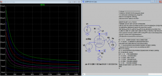
No, I'm unable to confirm it, according to my test sim putting 2 side by side, a change of KG2 does not make any difference to either model. It could be the improvement of Koren's model is more accurate as you can see formula for E1 & G1 is quite different.
Oh not the formula, I replace the original Koren's model data with the data I captured, the plot is the same!, it has something to do with original data, try to replace yourself, see below:
SUBCKT ECL84P 1 2 3 4
*X1 1 2 3 4 PENTODE1 MU=43.66 EX=1.350 KG1=344.3 KG2=4500 KP=201.06 KVB=26.0 VCT=0.00 RGI=2000 CCG=6.7p CPG1=0.6p CCP=4.1p ;
X1 1 2 3 4 PENTODE1 MU=43.5 KG1=615.6 KP=125.8 KVB=16.2 KVC=1.57 VCT=0.00264 EX=1.67 KG2=4500 RGI=2000 CCG=6.7p CPG1=0.6p CCP=4.1p ;
.ENDS
Ok sorry about the confusion over KG2, which indeed has effect on screen current (i overlook earlier). Now I change KG2 to 700 and KVC to 1.85 to get screen current (170V) close to original data sheet. However there is no corresponding on the other model (only KVB and KG2, with the formula on I am unable to obtain the accurate screen current plot.
**** ECL84 ******************************************
* Created on 10/01/2015 00:56 using paint_kip.jar
* www.dmitrynizh.com/tubeparams_image.htm
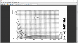
* Plate Curves image file: ecl84.png
* Data source link: <plate curves URL>
*----------------------------------------------------------------------------------
.SUBCKT ECL84P 1 4 2 3 ; P G2 G K
+ PARAMS: CCG=3P CGP=1.4P CCP=1.9P RGI=2000
+ MU=43.5 KG1=615.6 KP=125.8 KVB=16.2 KVC=1.85 VCT=0.00264 EX=1.67 KG2=700
* Vp_MAX=250 Ip_MAX=60 Vg_step=0.5 Vg_start=0 Vg_count=9
* Rp=1600 Vg_ac=23.5 P_max=4.01 Vg_qui=-23.4 Vp_qui=240 UL=0.43 EG2=170.4
* X_MIN=74 Y_MIN=121 X_SIZE=1029 Y_SIZE=615 FSZ_X=1790 FSZ_Y=827 XYGrid=true
* showLoadLine=n showIp=y isDHP=n isPP=n isAsymPP=n isUL=n showDissipLimit=y
* showIg1=n gridLevel2=n isInputSnapped=n
* XYProjections=n harmonicPlot=y harmonics=y
*----------------------------------------------------------------------------------
RE1 7 0 1G ; DUMMY SO NODE 7 HAS 2 CONNECTIONS
E1 7 0 VALUE= ; E1 BREAKS UP LONG EQUATION FOR G1.
+{V(4,3)/KP*LOG(1+EXP((1/MU+(VCT+V(2,3))/V(4,3))*KP))}
G1 1 3 VALUE={(PWR(V(7),EX)+PWRS(V(7),EX))/KG1*ATAN(V(1,3)/KVB)}
* Alexander Gurskii screen current, see audioXpress 2/2011
RE2 8 3 1G ; Dummy
G2 8 3 VALUE={(PWR(V(7),EX)+PWRS(V(7),EX))/KG2*(KVC-ATAN(V(1,3)/KVB))}
E2 8 4 VALUE={0} ; Dummy
RCP 1 3 1G ; FOR CONVERGENCE
C1 2 3 {CCG} ; CATHODE-GRID 1
C2 1 2 {CGP} ; GRID 1-PLATE
C3 1 3 {CCP} ; CATHODE-PLATE
R1 2 5 {RGI} ; FOR GRID CURRENT
D3 5 3 DX ; FOR GRID CURRENT
.MODEL DX D(IS=1N RS=1 CJO=10PF TT=1N)
.ENDS
*$
**** ECL84 ******************************************
* Created on 10/01/2015 00:56 using paint_kip.jar
* www.dmitrynizh.com/tubeparams_image.htm
* Plate Curves image file: ecl84.png
* Data source link: <plate curves URL>
*----------------------------------------------------------------------------------
.SUBCKT ECL84P 1 4 2 3 ; P G2 G K
+ PARAMS: CCG=3P CGP=1.4P CCP=1.9P RGI=2000
+ MU=43.5 KG1=615.6 KP=125.8 KVB=16.2 KVC=1.85 VCT=0.00264 EX=1.67 KG2=700
* Vp_MAX=250 Ip_MAX=60 Vg_step=0.5 Vg_start=0 Vg_count=9
* Rp=1600 Vg_ac=23.5 P_max=4.01 Vg_qui=-23.4 Vp_qui=240 UL=0.43 EG2=170.4
* X_MIN=74 Y_MIN=121 X_SIZE=1029 Y_SIZE=615 FSZ_X=1790 FSZ_Y=827 XYGrid=true
* showLoadLine=n showIp=y isDHP=n isPP=n isAsymPP=n isUL=n showDissipLimit=y
* showIg1=n gridLevel2=n isInputSnapped=n
* XYProjections=n harmonicPlot=y harmonics=y
*----------------------------------------------------------------------------------
RE1 7 0 1G ; DUMMY SO NODE 7 HAS 2 CONNECTIONS
E1 7 0 VALUE= ; E1 BREAKS UP LONG EQUATION FOR G1.
+{V(4,3)/KP*LOG(1+EXP((1/MU+(VCT+V(2,3))/V(4,3))*KP))}
G1 1 3 VALUE={(PWR(V(7),EX)+PWRS(V(7),EX))/KG1*ATAN(V(1,3)/KVB)}
* Alexander Gurskii screen current, see audioXpress 2/2011
RE2 8 3 1G ; Dummy
G2 8 3 VALUE={(PWR(V(7),EX)+PWRS(V(7),EX))/KG2*(KVC-ATAN(V(1,3)/KVB))}
E2 8 4 VALUE={0} ; Dummy
RCP 1 3 1G ; FOR CONVERGENCE
C1 2 3 {CCG} ; CATHODE-GRID 1
C2 1 2 {CGP} ; GRID 1-PLATE
C3 1 3 {CCP} ; CATHODE-PLATE
R1 2 5 {RGI} ; FOR GRID CURRENT
D3 5 3 DX ; FOR GRID CURRENT
.MODEL DX D(IS=1N RS=1 CJO=10PF TT=1N)
.ENDS
*$
Attachments

Last edited:
I have tried to use those models, but there are problems. First of all, parameter KG1 in triode definition is KG1=¡Þ. What is the correct value for KG1 in triode section?
Also, when I put this code into Multisim, I get warning: "Use of log() is ambiguous, simulation will treat this as ln() in this case."
But it is not a problem, I have tried to set KG1 to 300 and changed log to ln, but Multisim still can't run simulation with those parts, I always get convergence error. Does anyone have a clue how to fix this? The same circuit works fine with Multisim's 12AX7.