Not puttiing a "good" cap on a regulators output, & the reasons why, were suggested on another thread by either krglee or keantoken ? I couldn't locate the actual post/s, hence my posting here.
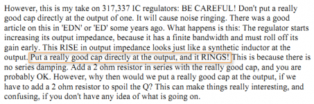
Interestingly i found this on Page #117 in John Curls's WoW PDF i'm currently reading. = Words of Wisdom 😉
Interestingly i found this on Page #117 in John Curls's WoW PDF i'm currently reading. = Words of Wisdom 😉
Attachments
I don't think you need 2 ohms, that's a bit overkill. I used a big cap with I think from memory 0.3 ohms in series on my LM317 based supply and it is perfectly happy 🙂
But yes the regulator has a certain amount of inductance which will form a resonant circuit with a really low ESR cap, you need some resistance to damp that resonance.
Tony.
But yes the regulator has a certain amount of inductance which will form a resonant circuit with a really low ESR cap, you need some resistance to damp that resonance.
Tony.
read the warnings in the low drop out regulator datasheets to see what generally applies to many other types of circuits.
An excellent way to gain a deeper understanding of the effect, is to put together a circuit simulation of a Sulzer-type voltage regulator: ideal voltage reference, IC opamp, NPN power transistor, and resistor voltage divider. Plot the open loop frequency response for various configurations of output capacitor: low ESR + low ESL + no series damping resistor, electrolytic + series 2 ohms, electrolytic + no series resistor, film cap + 2 ohms, film + no series resistor, etc.
This type of simulation will show you what goes wrong in any high-NFB voltage regulator with a capacitor on the emitter follower output. You'll see with your own eyes the "output pole", and how this creates a disastrous -40dB/decade rolloff that renders the regulator unstable. You'll also see how adding a resistor in series with the output capacitor, introduces a zero. This reduces the rolloff to -20dB/decade and restores stability to the feedback control system.
Beware: this is not a beginner-level project. Plotting open loop gain isn't simple, and extracting pole/zero locations from Bode plots can sometimes be a challenge. But if you've already succeeded in simulating the open loop gain of a discrete power amplifier, and .MEASured phase margin & gain margin, then simulating a voltage regulator such as this is only a half-step more difficult.
Design tips: (1) include a load resistor that draws a reasonable, non-zero amount of DC current from the regulator: ~20 mA for a preamp regulated supply, ~2A for a power amp "chip amp" regulated supply. (2) you can use an ideal voltage source for the voltage reference, but you CAN'T use an ideal VCVS for the error amplifier. Most of the evil {hence most of the learning!} in the voltage regulator results from having at least one pole in the opamp AND another pole at the output from the output capacitor. (3) start with a BJT output device instead of a MOSFET; I recommend the venerable D44H11 used by Walt Jung. This will make hand-checking the poles and zeroes quite easy, since the re of a BJT is well known and extremely well controlled: re = (1/gm) = ((kT/q) / Ic)
- Status
- Not open for further replies.