Nico, I am sorry for suggesting that you were interpreting the graphs wrong. However I am well aware of how BW and transient response correlate, as I watch it often with the simulator. Also the only way the regulator would saturate is if the amp broke, so there is no worry of long recovery times, which only occur after saturation. Am I wrong?
The basis for a 100mA shunt current is that if we want a regulator to exceed simple electrolytic capacitors in specs, the pass device needs to be passing enough current to lower the reg's output impedance. The other alternative is to add more active components, which would almost certainly adversely affect speed.
A friend sent me some interesting pages:
Power Supplies
Power Supplies
- keantoken
Jacco, I've played around with things like this on the simulator. Most series regs, when you REALLY test heir behavior, have pretty foul negative pulse response. I tried to fix this by using a class AB output stage on series regs, just like in amplifiers. As it turns out this is difficult, especially since it's slewing behavior you're trying to correct and at these frequencies class AB is not a good idea. A better way I'll bet is to hang a gyrator (like the JLH Riple Eater) at the output, which can be faster and will absorb part of the load.
- keantoken
- keantoken
....Hmmmm
I can not seem to source the LSK389A except seperately from one supplier. And of course RFQ it.
(It's mine! ALL MINE!!! )
)
Seriously, anyone else have an input to this quandry?
Sourcing for the other components almost complete with MS Excel BOM. 😱

The HS is going to be a 'one-off' dooozie.

Kean, I thank you for your hard work. Been looking around on the net for a very long time for a mixed amp design, and this is IT!!! Also kudos to Salas, OS, Jay, Andrew, Jam, mlloyd, and a few others (many posts ago
) for the inspiration for such a design. And never to forget Naggy for starting the fire!!!
I am no EE, but a tech only. I can build it. but no ee designs here. 😱
I can't hardly wait for this one!!!!!
Ok, ok, ok, (me no talkie, i must workie, workie)
I can not seem to source the LSK389A except seperately from one supplier. And of course RFQ it.
(It's mine! ALL MINE!!!
) Seriously, anyone else have an input to this quandry?
Sourcing for the other components almost complete with MS Excel BOM. 😱
The HS is going to be a 'one-off' dooozie.
Kean, I thank you for your hard work. Been looking around on the net for a very long time for a mixed amp design, and this is IT!!! Also kudos to Salas, OS, Jay, Andrew, Jam, mlloyd, and a few others (many posts ago
) for the inspiration for such a design. And never to forget Naggy for starting the fire!!!
I am no EE, but a tech only. I can build it. but no ee designs here. 😱
I can't hardly wait for this one!!!!!
Ok, ok, ok,
(me no talkie, i must workie, workie)
Last edited:
played around with things like this on the simulator.
Ah, but i wasn't referring to a series reg.

(AP SYS2 tested good enough ?)
More specifically, series regs tend to have very asymmetrical slewing.
If by push-pull you mean to rig the CCS to modulate as well, it could be done but might be difficult with MOSFETs because of the reactivity, and would likely decrease input isolation.
Kbeist, you can use the 2SK389, or matched 170's. There are members here who also know how to adjust the circuit to your particular choice of Jfet.
- keantoken
There are members here who also know how to adjust the circuit to your particular choice of Jfet.
CCS adjust trimmer... anyone. 😀 (also , different cascode collector resistors - 820-900R etc.)
OS
Kean,
...............so how goes the design of the regulator?
Jam
Yeah,
 I am just itching to put the finishing touches on a front end board...
Thanks 😀
Attachments
2SJ162/2SK1058
Are these good to go for the output of this project as far as FETs?
Will 80 volt rails B ok?😕
The board I am doing will give a choice of where you cut it to have from 2 to 6 pairs. 😀
Input please.
Thanks and lets us all PLEASE not let this project fade out...😉
Are these good to go for the output of this project as far as FETs?
Will 80 volt rails B ok?😕
The board I am doing will give a choice of where you cut it to have from 2 to 6 pairs. 😀
Input please.
Thanks and lets us all PLEASE not let this project fade out...😉
2pair of Lateral mosFETs fed from +-80Vdc rails is not a good recipe for good performance.
4 to 6pair will perform but are expensive.
4 to 6pair will perform but are expensive.
T6 - Is inverted ? Or not ?
Hi all,
from first schematic of Goldmund Amp in this thread, we see T6 as inverted configuration. Is this correct ?
Look this:
http://www.analog.com/static/import...tes/58052492001115525484056221917334AN211.pdf
eD
Hi all,
from first schematic of Goldmund Amp in this thread, we see T6 as inverted configuration. Is this correct ?
Look this:
http://www.analog.com/static/import...tes/58052492001115525484056221917334AN211.pdf
eD
Attachments
Last edited:
He is talking about the difference between schema in post #1 and the "other side"'s schema, where T6 is connected in another way.
A member explained me that
BTW, the "other side" means http://www.diyaudio.com/forums/solid-state/174468-very-best-amplifier-i-have-ever-heard.html.
Regards,
Max.
A member explained me that
T6 is set up as a simple diode shunted to the zener , it really serves little purpose. It is not a current mirror. A 2 transistor or diode/led shunted CCS would be more reliable and offer better PSRR.
BTW, the "other side" means http://www.diyaudio.com/forums/solid-state/174468-very-best-amplifier-i-have-ever-heard.html.
Regards,
Max.
Last edited:
I found the answer
http://www.diyaudio.com/forums/group-buys/175296-pcb-order-goldmun-clone-11.html
on page 11 and post# 102
Regards,
eD
http://www.diyaudio.com/forums/group-buys/175296-pcb-order-goldmun-clone-11.html
on page 11 and post# 102
Regards,
eD
Oops, Yahoo has been putting a lot of DIYAudio posts in the spam folder... Along with Emails sent to me by other people.
I haven't been able to try testing the regulator with my signal generator.
- keantoken
I haven't been able to try testing the regulator with my signal generator.
- keantoken
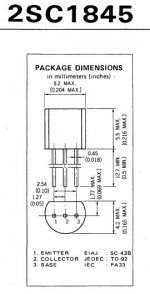
Krisfr, the top transistors are all TO92, this is not right. The 2 KSA1381's are TO126.
Furthermore, the bottom current mirror transistors are KSC1845's - TO126.
We're getting there...
Jacco and/or others, could you post an example of a very good layout for the FETs?
- keantoken
Furthermore, the bottom current mirror transistors are KSC1845's - TO126.
We're getting there...
Jacco and/or others, could you post an example of a very good layout for the FETs?
- keantoken
Yes, that transistor was inverted in the original design. I'm still not sure what there is anything to gain from this.
- keantoken
- keantoken
Attachments
Last edited:
- Home
- Amplifiers
- Solid State
- Goldmund Mods, Improvements, Stability