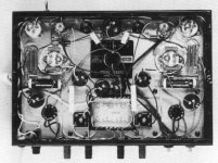
I really like that 4D32 design.
i have one in the works....
Attachments
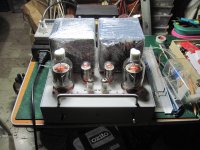
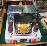
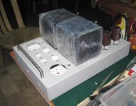
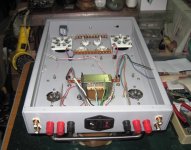
those are metal boxes i asked to be fabricated, the OPT's are EI's so with the power traffo...i have a replacement traffo to install to get a higher B+...
Attachments
-
 367B35E8-30F2-49ED-A879-9FF3855AD76F.JPG244.8 KB · Views: 270
 -
 F4280629-0545-4DCB-BBEA-BC0A1EDBC86B.JPG665.2 KB · Views: 415
 -
 9CECDC40-CE49-478A-A156-E0B00B6D35DA.JPG386.1 KB · Views: 428
 -
 30BA8949-EA5F-4C95-A843-DFBDC32ED7C4.JPG384.7 KB · Views: 288
 -
 ACB1457A-4515-4608-91A9-C17198815275.JPG396 KB · Views: 669
 -
 4092C8A3-24EE-4072-84E5-B2ED313FFFC8.JPG223.7 KB · Views: 388
 -
 015AB161-ED0C-4A0F-9437-E2D532D2F88F.JPG535.9 KB · Views: 362
 -
 193FEA46-DE67-435A-B682-6743F9209C74.JPG335.6 KB · Views: 282
 -
 148B205B-3744-4FD2-A2D2-5F1C080C5392.JPG321.8 KB · Views: 404
 -
 6A8C6923-34C3-4902-91DF-08CDC21B87A9.JPG732.9 KB · Views: 387
Hello,
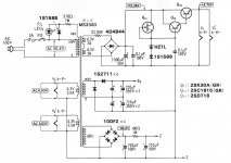
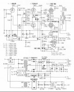
A quick question regarding the schematic with the 2SK117 CCS in the previous post. Does the negative voltage need to be fine filtered for this to work? Couldn't the the second RC filter be omitted?
A quick question regarding the schematic with the 2SK117 CCS in the previous post. Does the negative voltage need to be fine filtered for this to work? Couldn't the the second RC filter be omitted?
Attachments
-
 4742BBBA-11A1-4F25-8DB2-5E9B44FCB3A2.JPG358.8 KB · Views: 241
 -
 37E6F090-015A-45BC-A085-35278F7DCDBC.JPG314.3 KB · Views: 247
 -
 05E71C9F-E812-4849-9C1E-0663331C0443.JPG310.4 KB · Views: 264
 -
 967A2843-EB8B-41C2-A304-E5A155DCE810.JPG438 KB · Views: 174
 -
 B1A1ED9B-DD26-4149-AEE3-236FCDE4191E.JPG545.8 KB · Views: 174
 -
 1FB0A6CE-D2FA-4627-8C5B-70ECBD9F0B9C.JPG564.2 KB · Views: 221
 -
 8DD1F469-1827-4494-91B1-EC2FCE9E1898.JPG254.7 KB · Views: 170
 -
 6F8ED62D-3364-4EBD-83B8-2FC1FE37C5D4.JPG376 KB · Views: 257
 -
 D3047439-259E-498B-9717-8BDF381A6C33.JPG399.3 KB · Views: 240
 -
 BE201A68-9056-4E7E-AA70-58BC8134C172.JPG97.4 KB · Views: 229
+


Attachments
-
 0672F586-6C04-4BAC-AD01-29D6D8DAAC5F.JPG259.5 KB · Views: 187
 -
 80934A1F-B695-4F55-9679-FBC0AD3B36D9.JPG264.6 KB · Views: 276
 -
 1A0E3676-751F-437F-A6D3-F0FEF468B442.JPG670.5 KB · Views: 218
 -
 E9F6C344-4570-4B19-9D69-15D16D1CF36C.JPG133.9 KB · Views: 157
 -
 CDC340BE-C3EF-4DDD-9F09-AFFCB8511EA8.JPG423.3 KB · Views: 255
 -
 28468A2D-5709-4624-A15A-A9819503757A.JPG416.3 KB · Views: 262
 -
 63641D58-3D4D-448C-9735-2573ECCBEAF0.JPG285.7 KB · Views: 274
 -
 507E0AC6-C34B-4D5E-A9CC-45BBAEAAA50B.JPG255.6 KB · Views: 248
 -
 87B5B5A0-9165-42EB-9478-ED803F3BBED1.JPG287.6 KB · Views: 280
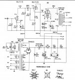
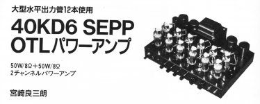
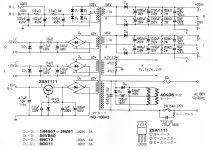
They're feeding the 40KD6 heaters directly off the mains in that OTL 😱😱!
Best regards!
Let's say is an old design from the 90´s


Yes, the heater to cathode insulation is NOT a safety device! On the contrary, all tube manufacturers advised to connect the heater to the cathode via a resistor of a specified maximum value.
Best regards!
Best regards!
As always, Safety First!
Prevent the "Surviving Spouse Syndrome"
A general statement that filaments and cathodes should be tied together by a 'recommended' resistor (not just the 40KD6 tubes), depending on the circuit topology, can have both safety and performance implications.
A few Newbies might be confused, and might build either an Un-Safe circuit, or a Low Performance circuit, or both at the same time.
Please, tell me I am missing some important point . . .
If you start with a concertina phase splitter stage, and then tie the heater to the cathode with the recommended 10k or 20k Ohm resistor, the Concertina performance will be degraded.
It will be true, whether the filament is AC or DC powered, if the filaments share a common supply.
And, if you start with an LTP phase splitter, and then tie the heater to the cathode with the recommended 10k or 20k Ohm resistor, then that phase splitter performance will be degraded.
It will be true, whether the filament is AC or DC powered, if the filaments share a common supply.
With a single AC or DC powered filament supply all the cathodes will be resistively tied together by the suggested filament to cathode resistances.
Floating Cathodes will no longer be floating, and many circuit topologies Require 'floating' cathodes that are not tied to another circuit by a 10k or 20k resistor.
Just my 2 pennies worth.
Last edited:
They're feeding the 40KD6 heaters directly off the mains in that OTL 😱😱!
Best regards!
perhaps, they found that 100vac was not lethal enough.....but that is one practice i will never copy....
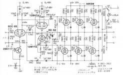
@6A3summer: All datasheets (at least those that I know 😉) on AF tubes that could be used in PI applications explicitely allow higher cathode to heater restistances here.
Best regards!
Best regards!

Attachments
-
 B4641F30-006D-4E33-BC18-306B5DC78A70.JPG528.6 KB · Views: 356
 -
 CA95715A-144D-4C7E-A43D-9F306C75F213.JPG294.4 KB · Views: 372
 -
 414F10C9-38AB-403A-A2A6-6441357AEBAF.JPG473.8 KB · Views: 370
 -
 23FB1BAD-91C6-4446-BBF0-007A47F344A3.JPG255 KB · Views: 387
 -
 4813211E-ED6B-4DBF-87CB-4966FF0A27CF.JPG606.4 KB · Views: 246
 -
 3CE9FB51-EA3B-436D-AE80-FA6DF0A27973.JPG457.9 KB · Views: 237
 -
 36956018-C1F2-4D58-B13D-D6686F19AA13.JPG314.6 KB · Views: 239
 -
 0C1398B5-07EA-400A-A998-23A838F33A77.JPG255.4 KB · Views: 232
 -
 31F7F529-D6D2-4D06-94A8-AF59197EC046.JPG315.1 KB · Views: 251
 -
 FF056B5F-F8CC-4E8C-84D5-5E78943BA1B1.JPG251.9 KB · Views: 169

Attachments
-
 0E787C8A-8A84-40DE-ADA8-3ECFD9B88B62.JPG323.6 KB · Views: 195
 -
 CDCA707A-486C-4947-B4D9-E63188C8442E.JPG261.9 KB · Views: 210
 -
 4050F3DA-C94F-43E8-91F6-3596F0BF0011.JPG381.9 KB · Views: 228
 -
 9E6E4E88-7443-4497-95DF-7EAECDC5AE25.JPG397 KB · Views: 213
 -
 EDF10BB2-62DF-464E-863F-46AE3F43DC78.JPG219.4 KB · Views: 149
 -
 17A35E32-6609-49BC-B8A6-FFF73B9733A3.JPG562.1 KB · Views: 180
 -
 0A677C8C-BCE7-4127-8164-425F00717EA1.JPG594 KB · Views: 190
 -
 3B11C021-1A68-4F96-AAA2-54E8B22CA264.JPG324.6 KB · Views: 230
 -
 938AB584-BB8B-4143-B181-740543F4AE62.JPG110.1 KB · Views: 229
 -
 76E9C458-97BA-4525-B63A-86FB20D03D07.JPG126.3 KB · Views: 197
どうもありがとうございます
Domo arigato gozaimasu
to Old Radio Boy from Japan and Diyers Friends
for all schematics sharing and contributions
😀 Peace and Joy to All Merry Christmas
Domo arigato gozaimasu
to Old Radio Boy from Japan and Diyers Friends
for all schematics sharing and contributions
😀Peace and Joy to All Merry Christmas Attachments
-
 0D73E321-6D91-4F20-B03D-346E4BB8937D.JPG163 KB · Views: 115
 -
 6B3A2AA7-0ACC-43C0-9E4D-02552DB821A8.JPG478.2 KB · Views: 189
 -
 1BB3611B-240A-4953-A0D3-12D167629A38.JPG381.7 KB · Views: 248
 -
 1A87C10C-DBFE-46D1-9EF6-E3B5252E412D.JPG642.4 KB · Views: 251
 -
 786BE11A-C4BD-489C-8704-DE10B1BCA6DA.JPG345.7 KB · Views: 250
 -
 87B64D37-8238-44E2-9BD7-163D0F0A96D1.JPG459.7 KB · Views: 219
 -
 5B2038F3-2284-4DC8-A97A-D864450DDC32.JPG54.1 KB · Views: 124
- Home
- Amplifiers
- Tubes / Valves
- Gold mine of DI¥ audio tubes schematics from Japan