According to the previous owner this blows fuses. I was able to find the technical manual, so I have a ton of info.
So just starting out at this hobby, would the best starting point be to try and understand the flow of power through this and understand what each component does? Being just an average person with good troubleshooting skills and a dmm, will this take weeks, months or years to learn to do? I'm building a dim light tester too, but don't even understand why.
So just starting out at this hobby, would the best starting point be to try and understand the flow of power through this and understand what each component does? Being just an average person with good troubleshooting skills and a dmm, will this take weeks, months or years to learn to do? I'm building a dim light tester too, but don't even understand why.
Attachments
It takes about 10 minutes to learn to repair the simplest faults on the simplest amps. Since amps continue to evolve, you never really learn or know everything.
If the amp only blows the fuse after remote voltage is applied, the most likely problem is shorted output transistors. If it blows the fuse with only B+ and ground connected, the problem is likely shorted PS FETs or a shorted reverse-protection diode.
If the amp only blows the fuse after remote voltage is applied, the most likely problem is shorted output transistors. If it blows the fuse with only B+ and ground connected, the problem is likely shorted PS FETs or a shorted reverse-protection diode.
Thanks Perry. I hooked her up and I can't get it to blow the fuse like the guy said. No sound and the power light doesn't light up.
If you have 0, 12, 0v DC on the 3 legs of each power supply FET, post the DC voltage on all legs of the TL494 (IC1). Copy and paste the following in your post:
Pin 1:
Pin 2:
Pin 3:
Pin 4:
Pin 5:
Pin 6:
Pin 7:
Pin 8:
Pin 9:
Pin 10:
Pin 11:
Pin 12:
Pin 13:
Pin 14:
Pin 15:
Pin 16:
Pin 1:
Pin 2:
Pin 3:
Pin 4:
Pin 5:
Pin 6:
Pin 7:
Pin 8:
Pin 9:
Pin 10:
Pin 11:
Pin 12:
Pin 13:
Pin 14:
Pin 15:
Pin 16:
OK I will do this. I assume I power up the amp, connect one lead to ground (chassis ground?) and then poke the legs? I don't want to assume anything and ruin any components.
OK I removed the board. So I can apply power with the fets unclamped? What about the chassis grounds, do I need to ground them to something? I have a bunch of aluminum angle and some taps, should I rig up a heatsink?
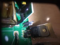
I saw one component that I wasn't sure about a 10k ntc thermistor, I measured it and got 3.5k at room temp. I'm including a pic.
I saw one component that I wasn't sure about a 10k ntc thermistor, I measured it and got 3.5k at room temp. I'm including a pic.
Attachments
If it's not powering up, there is little risk to the heatsink mounted components. It's going to be an issue if/when the amp is operating out of its heatsink.
The thermistor is connected to other components that could be making it read low in the board.
For this type of amp, the ground screws on the board aren't critical for the amp to function.
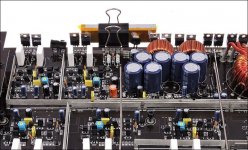
For a temporary heatsink, there's no need to get fancy. Aluminum bar or angle with office supply bider clips work well enough. The insulators have to be installed so the metal-backed components can't short to the heatsink. The binder clips also have to be clear of the metal parts of the semiconductors. The attached image shows bar stock (doesn't need to be that thick) with kapton tape as the insulator.
The thermistor is connected to other components that could be making it read low in the board.
For this type of amp, the ground screws on the board aren't critical for the amp to function.
For a temporary heatsink, there's no need to get fancy. Aluminum bar or angle with office supply bider clips work well enough. The insulators have to be installed so the metal-backed components can't short to the heatsink. The binder clips also have to be clear of the metal parts of the semiconductors. The attached image shows bar stock (doesn't need to be that thick) with kapton tape as the insulator.
Attachments
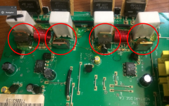
Here's a pic where I circled the components I just measured. The center leg on all 4 was 0 volts and the power wire going into the amp from my power supply reads .03 volts when its hooked up to the amp and the power supply is on. I checked the power supply when its not hooked up to this amp and it puts out 13 volts.
Attachments
If you haven't done so, read the basic amp repair page in the sig line below.
Those are driver transistors, not the power supply transistors. The PS FETs are Q30 and Q31.
Those are driver transistors, not the power supply transistors. The PS FETs are Q30 and Q31.
OK ill read the guide. Thanks for your help. And the center legs on q30 and q31 are .01v and 0v.
I can't see anything definitive. There may be some questionable solder connections.
Black probe on the ground terminal...
Touch your red probe to
both sides of the fuse
both terminals of L4
all primary terminals of the power transformer
Where do you lose 12v?
Black probe on the ground terminal...
Touch your red probe to
both sides of the fuse
both terminals of L4
all primary terminals of the power transformer
Where do you lose 12v?
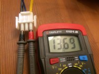
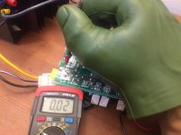
Here is a pic showing the wiring that came with the amp hooked to the power supply and another pic measuring one of the pads the fuse holder is soldered to. The other side of the fuse measures .02v. I can measure the wires where they go into to molex connector and get the same .03v and .02v readings.
L2 reads .01v L4 reads 0v
That is a special protective glove I am wearing, not my actual hand, in case you are wondering.
L2 reads .01v L4 reads 0v
That is a special protective glove I am wearing, not my actual hand, in case you are wondering.
Attachments
What's the resistance across B+ and ground on the amp? Maybe something is shorted and shutting the supply down.
- Home
- General Interest
- Car Audio
- Going to repair jbl gts100