Hi All
A friend asked me to try and repair his Marklin loco. I don't know what guage but it operates from 12Vdc and I have a piece of track to try it out on.
I have done the following until now - cleaned the tarnished piece of track to shiny copper, cleaned the compacted greasy grime from all wheels. Carefully checked all wire connections and re-soldered two suspected dry and frayed joints.
When done with all of the above, I set my bench powersupply to 12Vdc and applied the probes to the tracks and got it to run the length of the track.
The owner told me earlier, that besides intermittent running, the loco is supposed to reverse when polarity is switched. There is a contraption on top, forward of the motor which I also checked thoroughly and cleaned two contacts which were not particularly dirty.
Later this evening, I tried again. I can see the polarity contraption's solenoid work each time I apply power to the tracks but now, intermittently and continuously if power is applied to the tracks, the loco starts to move and then stops.
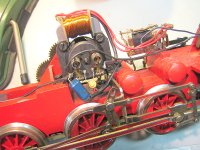
There are two parts visible in my pic - one has a blue plastic sheath but it doesn't look like an electronic component as there seems to be a piece of lead? inside with bare wires looped into holes. The other yellowish part appears to be some kind of starting capacitor for the motor.
If this part is open circuit (can't test it and I don't know its value), would anyone know what to replace it with?
Thanks
bulgin
A friend asked me to try and repair his Marklin loco. I don't know what guage but it operates from 12Vdc and I have a piece of track to try it out on.
I have done the following until now - cleaned the tarnished piece of track to shiny copper, cleaned the compacted greasy grime from all wheels. Carefully checked all wire connections and re-soldered two suspected dry and frayed joints.
When done with all of the above, I set my bench powersupply to 12Vdc and applied the probes to the tracks and got it to run the length of the track.
The owner told me earlier, that besides intermittent running, the loco is supposed to reverse when polarity is switched. There is a contraption on top, forward of the motor which I also checked thoroughly and cleaned two contacts which were not particularly dirty.
Later this evening, I tried again. I can see the polarity contraption's solenoid work each time I apply power to the tracks but now, intermittently and continuously if power is applied to the tracks, the loco starts to move and then stops.
There are two parts visible in my pic - one has a blue plastic sheath but it doesn't look like an electronic component as there seems to be a piece of lead? inside with bare wires looped into holes. The other yellowish part appears to be some kind of starting capacitor for the motor.
If this part is open circuit (can't test it and I don't know its value), would anyone know what to replace it with?
Thanks
bulgin
Attachments
The yellow part looks like a varistor or MOV used to absorb the back EMF when the solenoid is switched.
The blue part looks like a capacitor and may be for reducing interference generated by the brushed motor. It will test open circuit on multimeter but you should be able to read its value off the body. You may have to cut the plastic sheath to get a good look.
The blue part looks like a capacitor and may be for reducing interference generated by the brushed motor. It will test open circuit on multimeter but you should be able to read its value off the body. You may have to cut the plastic sheath to get a good look.
Thanks guys😀
I'll look at the motor brushes as well. One looks dodgy and it looks as if someone has stuffed a piece of brass gause in there.
Regds
bulgin
I'll look at the motor brushes as well. One looks dodgy and it looks as if someone has stuffed a piece of brass gause in there.
Regds
bulgin
Definitely check brushes. They look very recessed, as if worn almost away. You may also wish to take motor apart and clean up commutator. Be careful not to break any small wires.
Doc
Doc
Definitely check brushes. They look very recessed, as if worn almost away. You may also wish to take motor apart and clean up commutator. Be careful not to break any small wires.
Doc
Thank you. I will check and replace brushes if necessary. I have suitable brush material and usually turn 'raw' brush material down in my lathe - a messy job.
Regds
bulgin
Hi Mark
Thanks for looking. Regarding you question - I don't know. I'm trying to repair the loco for a friend. I am a member of an engineering society and we have a couple of electrical and electronic engineers as members.
So I took it along last night and we had a 4-panel 'conference' about the problem. We did some multimeter measurements and found all wheels tested positive for continuity between the wheels on both sides and the chassis, as well as most other metal parts. That was why my bench power supply indicated shorting if 12Vdc is supplied to the two rails - ie + to one rail and - to the other.
The loco's owner says its a Guage 1 type loco and doesn't use a 3-rail track.
I'm busy trying to contact local Marklin train guys to see if they have any more ideas. For now, I suspect an insulation breakdown somewhere - probably through age.
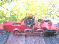
Here it is - full Monty😀
bulgin
Thanks for looking. Regarding you question - I don't know. I'm trying to repair the loco for a friend. I am a member of an engineering society and we have a couple of electrical and electronic engineers as members.
So I took it along last night and we had a 4-panel 'conference' about the problem. We did some multimeter measurements and found all wheels tested positive for continuity between the wheels on both sides and the chassis, as well as most other metal parts. That was why my bench power supply indicated shorting if 12Vdc is supplied to the two rails - ie + to one rail and - to the other.
The loco's owner says its a Guage 1 type loco and doesn't use a 3-rail track.
I'm busy trying to contact local Marklin train guys to see if they have any more ideas. For now, I suspect an insulation breakdown somewhere - probably through age.
Here it is - full Monty😀
bulgin
Attachments
Last edited:
Hi, model railway days are back - in a way.
Märklin model railways were different from virtually all other brands in using AC and a three conductor system. Both tracks were one AC pin, the centre was the other
The control was a variac that supplied 0 to 16V of AC. The motor in the engine was a universal motor like in a power drill. It could run off AC ord DC. The field and the rotor were series connectod (like in a power drill). When the polarity in the rotor changes (from following the AC phase) the magnetic field in the stator would also change. So obviously changing the polarity does not the change the direction of the loco.
The old Märklin motors had two field coils that were wound in opposite directions.
One for each direction of transport. The relais in the loco got triggered by a pulse of higher voltage and switched from one field winding to the other for each pulse. Like a flip flop. You had to turn the control knob to the left to fire such a high voltage pulse.
For foreign ,markets where the three conductor track were not popular Märklin made special versions of their engines. Unlike the German ones their wheels must not have a connection between left an right wheels. The export versions still have universal motors (no permanent magnets). I guess they use the relais to change polarity on the stator coil to change direction of transport. You could use a rectifier to keep the staror field in the same direction (magnetically) when the polarity of the rotor is changed by changing the polarity of the voltage on tracks.
Hello Grommeteer
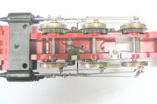
Perhaps a stupid question - how can the righthand set of wheels be electrically isolated from the lefthand set of wheels if all wheels are electrically connected by their axles?
Pic of the underside attached.
Regds
bulgin
Perhaps a stupid question - how can the righthand set of wheels be electrically isolated from the lefthand set of wheels if all wheels are electrically connected by their axles?
Pic of the underside attached.
Regds
bulgin
Attachments
Last edited:
Could it be that the set of wheels that is at the bottom of the picture has some kind of plastic isolation where it is fitted to the axle? A grommet of some kind;-) ? It is interesting that those wheels have slipping contacts to pick up the current from the rail. While the top row of wheels seems to be connected to the chassis. They two sets of wheels must not be connected in a model railway without a centre power rail. Maybe your patient has an intermittent short circuit between the isolated wheels and the chassis. It is quite narrow between the wheels and the undercarriage.
Gesendet von meinem iPod touch mit Tapatalk
Gesendet von meinem iPod touch mit Tapatalk
I think I can see a little groove on the wheels of the rear axle. Märklin used to fit those grooved wheels with tyres, like rubber bands. They improve traction. I found it hard to keep the oil away from that rubber. If you don't mind the German text google Märklin HAMO for information on the two conductor DC version of their rolling stock. The carriages had isolated axles as well.
Gesendet von meinem iPod touch mit Tapatalk
Gesendet von meinem iPod touch mit Tapatalk
Hello again Grommeteer
As far as I can see, the axles are going into nylon/plastic bushes, thus showing isolation. I will look further. At this time the only way I can assume, is that some of the wheels could have had rubber 'tyres' but I'm not sure. When I cleaned the wheels, most of them already had bare metal in places. I +- expected some kind of rubber or hard plastic so I was very careful to use only turpentine to clean.
In the meantime, I made contact with a local group iof Maerklin train people in Johannesburg (I'm in Cape Town) and sent them some details of the problem this morning.
I once more thank you for your kind attention here and will report back. Thanks too for the link. I will have a look later.
Regards
bulgin
See red insulators on wheels on bottom side of picture? Brushes rub inside those wheels, but they are isolated at axles. Or should be.
Doc
Doc
I have done some reading and turned out that Märklin's DC engines did not come with a universal motor and a field or stator coil. They had a magnet in the place of the coil. That made the motors regular DC motors. No relay needed. Your little steam engine is different. Someone may have tried to convert it.
Gesendet von meinem iPod touch mit Tapatalk
Gesendet von meinem iPod touch mit Tapatalk
I have some experience in HO model trains, with DC motors not AC.
Traction tires were sometimes used to prevent excess wheel slippage, very common in the smaller scales and especially in the lighter plastic models. These were less common in heavy locomotives, the larger scales and those with all-metal construction. Traction tires would eventually wear out, break, or fall off. If a locomotive wheel has a groove in it that would be what held the rubber tire in place.
For 2-rail electrical operation the wheels are insulated, usually at one end of the axle but sometimes between the wheel center and the metal "tire" which contacts the track. The frame and body often were not insulated (nor electrically isolated), just the wheels on one side, and would short if contact is made with the opposite polarity. This is a tank locomotive which didn't require a tender (it carried its own water and coal), but model steam locomotives often used the tender for electrical pickup too, with the locomotive wheels drawing from one rail and the tender wheels from the other, which required an electrical connection from the tender to the loco. Depending on what portions of the model were insulated a locomotive might short out if it contacted the tender body, a railcar whose body was "wrong" polarity, or if a loose part made contact with the wrong part of the loco. Diagnosing an intermittent short could be a challenge, with any number of places where the problem may be.
Everything I remembered and wrote about is about Märklin H0. The more I read and think about I feel yours could be a size 1. Is the track spacing 45 mm?
Gesendet von meinem iPod touch mit Tapatalk
Gesendet von meinem iPod touch mit Tapatalk
Everything I remembered and wrote about is about Märklin H0. The more I read and think about I feel yours could be a size 1. Is the track spacing 45 mm?
Gesendet von meinem iPod touch mit Tapatalk
Jawohl, Herr Grommeteer. It is Guage 1 and the track distance is indeed 45mm apart. No reply from the local guys yet.
Regards
bulgin
- Status
- Not open for further replies.
- Home
- Member Areas
- The Lounge
- Going Loco