1. Build the headphone amp with it's dedicated 12:1 transformer.
Mount also a coupling capacitor from the anode of the C3g to an output RCA.
Input of the GM70 amp starts with a 100k resistor (from input to negative bias supply).
In this case we have full gain of the C3g because the primary of the IT acts like an anode
choke. But hmmm we have a capacitor.
I like this idea!😉
That means headphones will be IT coupled but GM70 cap coupled right?
Another reason that Im insisting on using the same C3g is because I already have RF remote volume controlling motorized ALPS pot and input selector in my current headphone amp that I can't live without.😛
If we build a new C3g driver stage in the GM70 amp, that means I will have to add in a volume control and connect all the sources directly.
I'll try to digest your suggestions and update a new schematic.
- Louis
seems C3g is said to be a fantastic tube
but Im not sure its so perfect with IT
its my understanding that IT's are best kept at low impedance, thus IT driver with low impedance are better choises
wouldnt it be much better to do a combined head/preamp, and the GM70 amp, as individual amps
but Im not sure its so perfect with IT
its my understanding that IT's are best kept at low impedance, thus IT driver with low impedance are better choises
wouldnt it be much better to do a combined head/preamp, and the GM70 amp, as individual amps
That was the whole idea!wouldnt it be much better to do a combined head/preamp, and the GM70 amp, as individual amps
To keep my headphone amp as the preamp for the GM70.
If Im not wrong, the discussion went on because the IT to drive my 64ohm cans is not optimal to drive GM70. And to find a better way to use fixed bias for GM70 when the IT is located in the preamp.
- Louis
Tinitus,
C3g triode connected has a mu of 40 and Rp of about 2k.
These are excellent parameters for IT 1:1 coupling.
Pieter
C3g triode connected has a mu of 40 and Rp of about 2k.
These are excellent parameters for IT 1:1 coupling.
Pieter
Tinitus,
C3g triode connected has a mu of 40 and Rp of about 2k.
These are excellent parameters for IT 1:1 coupling.
Pieter
thanks for correcting🙂
I thought I saw something with 10kohm, but must have been wrong specsheet
buggers, now Im interested too 🙄
ahh, it says Ri 2.3kohm, and Ra 15kohm
I suppose thats what confused me
Im getting closer to my final design now!
This is the schematic in the GM70 chassis.
Input resistor = 100K
Cathode resistors = 47ohm each
Any comments on the design?
As for the C3g chassis, I have drew 3 versions.
Version 1: IT with two taps. One for headphones, the other for GM70.
Version 2: Cap coupling for headphones, IT coupling for GM70.
Version 3: IT coupling for headphones, cap coupling for GM70.
My preference is v1, follow by v2, last is v3.
Which one do you guys prefer?
- Louis
This is the schematic in the GM70 chassis.
Input resistor = 100K
Cathode resistors = 47ohm each
Any comments on the design?
An externally hosted image should be here but it was not working when we last tested it.
As for the C3g chassis, I have drew 3 versions.
Version 1: IT with two taps. One for headphones, the other for GM70.
Version 2: Cap coupling for headphones, IT coupling for GM70.
Version 3: IT coupling for headphones, cap coupling for GM70.
An externally hosted image should be here but it was not working when we last tested it.
An externally hosted image should be here but it was not working when we last tested it.
An externally hosted image should be here but it was not working when we last tested it.
My preference is v1, follow by v2, last is v3.
Which one do you guys prefer?
- Louis
I wouldn't do version 2 if I were you 🙂 It won't work, try for yourself to find out why.
Whether v1 or v3 is better will be entirely up to the quality of the transformer.
Regarding the GM70 stage: The way you drew it now, the filament supply will need to be floating again. Also you need a resistor between the bias supply and the grid, otherwise you won't be able to superimpose an AC signal on it. And what is that 100K input resistor doing there??
Kenneth
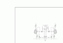
This is the right schematic for the input.
Version 1 is best.
In this case the bias supply can be built into the headphone amp.
The two secondaries cannot be "combined" be making a headphone "tap" but must be separated so that the negative bias voltage can be applied to the tail of the 1:1 winding, and the tail of the headphone winding can be connected to ground.
Making this transformer is in good hands here.
Pieter
Attachments
This is the right schematic for the input.
Version 1 is best.
In this case the bias supply can be built into the headphone amp.
The two secondaries cannot be "combined" be making a headphone "tap" but must be separated so that the negative bias voltage can be applied to the tail of the 1:1 winding, and the tail of the headphone winding can be connected to ground.
Making this transformer is in good hands here.
Pieter
Thanks Pieter!
Below are the updated schematics.
Any comments appreciated!
By the way, can the two channels share the same negative bias?
An externally hosted image should be here but it was not working when we last tested it.
An externally hosted image should be here but it was not working when we last tested it.
An externally hosted image should be here but it was not working when we last tested it.
An externally hosted image should be here but it was not working when we last tested it.
- Louis
By the way, can the two channels share the same negative bias?
Yes, if you give each channel its own bias potmeter.
are you sure your interstage wont give step down
what do you rate as optimal primary impedance on IT
btw, I have been recommended to run the C3g in penthode UL, through IT
what do you rate as optimal primary impedance on IT
btw, I have been recommended to run the C3g in penthode UL, through IT
Tinitus,
The schematic is very clear: step-down for the headphone, 1:1 to drive the GM70.
Primary impedance is determined by secondary load, so for the headphone the primary impedance is 64 x 12 x 12 = 9216 ohms.
To drive the GM70 through the 1:1 the C3g will see the very high impedance of the GM70 grid, therefore the C3g is virtually "unloaded" and hence will give all of it's gain of 40 (in triode).
I am curious who recommended you to run the C3g in pentode UL, never heard of it.
You can use interstage transformers for triodes (pure triodes or UL); pentodes are not suited.
Pieter
misunderstanding
I meant how you will wire interstage internally to give those specs, if its LL1660 as suggested
seems a Lundahl offers many different configurations, with varying specs
but regarding LL1660, each winding seem to have close to equal winding ratio
the only ones I can see with very different winding ratios are the low voltage versions
with LL1660 I dont see how more than 4:1 is possible
or there wouldnt be any winding left for 1:1
will a connected headphone affect the whole IT
and could it introduce noise issues
sorry Im confused, just ignore
Who suggested LL1660?
oh, my mistake, sorry
but still, designing an IT is on itself not a trivial task, even if "only" 1:1
like said, it appears to be a low voltage line trafo and high voltage IT, all in one
any IT with those specs
why not take signal to headphone through a cap, directly from plate/2.grid
and IT secondary to GM70 only
well, that was in your second scheme, but kavermei/Kenneth ruled that one out, so I guess not
Attachments
Tinitus,
Sorry......, but I get a bit tired of you.
You seem to be a moderator here, but you do not seem to read the thread properly before reacting; this results in your "mistakes" and "apologies".
As for the IT, I made over a hundred of these, custom, don't be afraid.
Your C3g headphone schematic will drive a 64 ohms headphone, but the step-down transformer will work much much better distortion wise than a coupling capacitor.
Pieter
- Status
- Not open for further replies.
- Home
- Amplifiers
- Tubes / Valves
- GM70 bias & IT ratio question

