I think "microphone effect" is even worse than using "back emf" to unnecessarily complicate amp-speaker interaction description
the voice coil "motor" is a electro-mechanical transformer that interconverts converts motion/velocity to V and force to current as seen at the electrical terminals of a dynamic driver
the nonlinearities of a dynamic driver when driven by a electrical source all can be modeled as nonlinear additions to the Theil-Small electrical terminal model
spend a few hours (or days) reading the material on the https://www.klippel.de/ site
a speaker's driver's nonlinear load characteristics will give nonlinear current that is converted to nonlinear V in any driving impedance, either from added series R or output device open loop Z divided by the feedback factor
when the amp has low feedback/nonlinear output Z the current output to a loudspeaker load gives very nearly the same amplifier distortion as any other load and signal that draws the same current - including resistive load under "quasi-static" conditions
then signal frequency, slew rate, amplitude approaching saturation give additional distortions
but you see more of a nonlinear load's current converted to V in the amp's higher output Z added in too
if you current drive a dynamic driver then the amp controls the current and the driver nonlinearities show up as compliance V added nonlinear terms - in symmetry with the more common V source drive condition where the driver nonlinearities show up as nonlinear load currents
Last edited:
If the speaker is designed to use a higher Source impedance, then the user manual should state so and explain how to achieve the effect that the Speaker Designer intended.
Naturally- and many such speakers do (although not the older horn systems from the 1950s... all amps had a fairly high output impedance back then, which is why such speakers have a mid and high frequency control to allow the speaker to be adjusted to the amplifier's voltage response).
It is not the fault of the amplifier, nor the amplifier Designer, that a speaker does not perform as intended when it is designed to suit a higher source impedance.
Correct- its simply an incompatibility. Any time a device intended to operate within the voltage rules is used with a device that is intended to operate within the power rules (or current rules) a tonal anomaly of some sort is quite likely. This BTW is at the root of the amplifier/speaker matching conversation that has existed for the last 50 years or so.


Let's assuming everything is ideal, will this work? 😀
In theory, "assuming everything is ideal" it could work. However (there's always a "however" when it comes to theory vs. reality) you would have to find a way to acoustically couple the speaker output perfectly to the mic while totally eliminating external influences from room reflections and such. Good luck doing that!
Mike
More than that -- you'll also have to do with the speed of sound (a fixed delay, expect instability). The mic can't be at the zero delay source point, that's usually about where the voice coil and front plate are.
Using a mic for servo feedback of a sub works pretty well, but you have to keep the bandwidth low with some pretty aggressive compensation. Hard to get enough feedback (while stable) to reduce harmonic distortion by much, but the FB can do wonders for compression (at fundamental frequencies) and for keeping response flat.
I made one a few years back using the mic (instead of the usual accelerometer), found it worked best to glue the mic capsule, sideways, right to the cone at the dust cap. It senses local pressure, and the electret capsules have limited signal handling so use of a large diameter woofer is a good thing to do.
I made one a few years back using the mic (instead of the usual accelerometer), found it worked best to glue the mic capsule, sideways, right to the cone at the dust cap. It senses local pressure, and the electret capsules have limited signal handling so use of a large diameter woofer is a good thing to do.
Nonlinear output Z is more a feature of high feedback designs, where the output Z begins to raise significantly already at frequencies below 10 kHz[...]when the amp has low feedback/nonlinear output Z [...]
What is a significant rise? 0.02 ohm up to ~10 kHz to 0.03 ohm at 20 kHz? How is this significant considering a 4 or even 8 ohm load?
I too would like to see measurements of significant rise below 10 kHz of typical designs or commercial products.
And then compare this to valve products where the output impedance is high to begin with and varies significantly over the whole audio range, resulting in significant frequency deviations. These amps should be renamed "fixed EQ amplifiers".
??Can you support this claim (rise in output z) with measurements..??
I do not think that I have to support this, it is simple math....
It is known and unavoidable that loop gain in high feedback designs decreases often already starting from 10-100 Hz.
Output Z is a direct function of available feedback (= loop gain) and therefore raises with frequency.
Look up OpAmp data sheets, and look for "Open Loop Gain vs Frequency".
If you subtract your desired gain from this curve, you get loop gain.
Power Amps are behaving exactly the same....it's an amp ath the end.
Maybe that's the reason some claim that OLG should be flat at least over audio band, which means that you have to reduce forward gain at LF.
However, I do not see any reason to have damping factors higher than say 20, but linear over frequency, as a solid state open loop amp has.
The small frequancy deviation because of this is way smaller than any speaker placement difference, in different rooms. Regardless how flat they are in an ancheoic room.
But going by the importance given here to such small deviations, methinks many here are listening and enjoying music in ancheoic rooms.
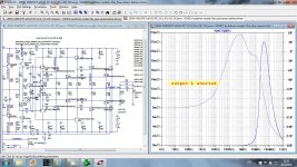
This is an amp with flat NFB up to 20 kHz and here the output protecting coil has much higher influence on the output impedance of the amp than the amp itself. With no coil the ouput impedance rises steady from 1.15 nohm to 19 uohm at 1 MHz.
Attachments

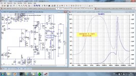
This is an amp with more typical decreasing NFB and, still, output inductor dominate the output impedance. The NFB lowers enough output impedance in whole audio range.
Attachments

Some are striving for "absolute measured performance".
So, if you have to use output inductor, it's even worse regarding linearity of output Z.
You don't really have to use it, with output stage not in a NFB loop.
So, if you have to use output inductor, it's even worse regarding linearity of output Z.
You don't really have to use it, with output stage not in a NFB loop.
This is of no significance what so ever, the impedance is always rising in speakers, unless you deal with electrostatics and some kind of ribbon tweeters. (they too will rise eventually) Feedback is not the reason for output Z to rise, the output coil is mandatory for two reasons 1. stability in capacitive loads and 2. to prevent RF entering backwards into amplifiers when your cable and speakers starts to work as an antennae.
My firm belief is that around the OPS is where you really need the feedback. You need it for two reasons, the primary to control the switching of your output devices and the secondary is exactly to make the amplifier an ideal Voltage source.
My firm belief is that around the OPS is where you really need the feedback. You need it for two reasons, the primary to control the switching of your output devices and the secondary is exactly to make the amplifier an ideal Voltage source.
Last edited:
"linear" doesn't mean independent of frequency in electronics
an inductive output Z is a Linear output Z if the inductor is Linear
and air core is practical for uH Audio Amp output series L
our electronic gain devices are power law - not inherently linear
practical low output Z comes from feedback - often local as in followers
so low output Z in practical electronic amplifiers is nonlinear
making it important to make the active device output Z contribution as low as possible if you want to reduce nonlinear output while sourcing output current to the load
the special case of Triode internal feedback having the same power law as the gain does give more linear output Z than the rest of our gain devices - if you accept the expense and inefficiency, requirement of output transformer costing more than the rest of the amp
Nonlinear output Z is more a feature of high feedback designs, where the output Z begins to raise significantly already at frequencies below 10 kHz
This has nothing to do with linearity or lack of it.
An increase in |Zout| is due to lack of loopgain - this is a linear entity.
\\\Jens
I think if you want to understand the real OP Z, you would need to include the circuit layout parasitics and real world component parasitics.
Last edited:
- Home
- Amplifiers
- Solid State
- Global Feedback - A huge benefit for audio