A PSRR plot is done with no input because you want to remove that as a variable and look at it in isolation.
If the PSRR varies with input that's something to characterize ISTM. In my sims I've found (just simming an OPS) that PSRR varies with output current. In a real-world situation (listening to music) there will be output current flowing so PSRR measurements (or simulations) with no signal present are only of academic interest.
Thoughts?
Hugh
My 2 cents with lesser explanation:
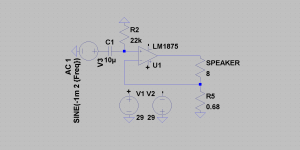
for me with minor issues (no damping of the speakers) this is (attached picture) the only way to use gnfb. All of my transconductance gnfb power amps are the winners vs voltage out gnfb power amps, both diy and commercial designs.
GNFB in preamps is excellent thing but probably for another thread.
Attachments
Last edited:
If the PSRR varies with input that's something to characterize ISTM. In my sims I've found (just simming an OPS) that PSRR varies with output current. In a real-world situation (listening to music) there will be output current flowing so PSRR measurements (or simulations) with no signal present are only of academic interest.
I am not aware of any studies showing PSRR varying with input signal. The loop gain varies AFAIK with frequency. PSU ripple will vary with load current, but going from that observation to the conclusion that it is the reason some find GNFB amps objectionable is a big step IMV.
If you have done sims share them - what is the underlying mechanism for your observation? Early effect maybe? C-B junction capacitance coupling hash on the rail to the output rail?
Any 'hash' from the OPS that finds its way to the LTP ends up exiting the LTP stage as a corrective signal that improves PSRR. If the amp is running OL, there is going to be no correction taking place other than local decoupling or any other techniques that are being applied. Please note this does not mean I am an advocate of sloppily designed OPS stages - but how can a well designed OPS with optimized PSRR in OL be deleteriously affected by the application of GNF if it further improves PSRR?
Finally: are suppressed PSU artifacts on a GNFB amp worse sounding than non- suppressed PSU artifacts in a ZFB amp - the question specifically wrt the OPS?
Last edited:
I'm happy with the way feedback works. But when listening to what subjectivists say about feedback it pays not to throw the baby out with the bathwater. They may say 'feedback causes poor sound' but they don't know this for sure (feedback being a concept only, it has no causal properties), what they're reporting is correlation between global negative feedback and poor sound. I have a hypothesis for why this is so and if anyone's interested in it I'll set it out here for the assembled company to shoot down 🙂
I'm all ears 🙂, I also have no problem with negative feedback, I think some might be confusing the global part of it. I like negative feedback loops used well, I do not like global feedback (ie: from the speaker terminal) to the inverting input.
Colin
I am not aware of any studies showing PSRR varying with input signal. The loop gain varies AFAIK with frequency. PSU ripple will vary with load current, but going from that observation to the conclusion that it is the reason some find GNFB amps objectionable is a big step IMV.
If you have done sims share them - what is the underlying mechanism for your observation? Early effect maybe? C-B junction capacitance coupling hash on the rail to the output rail?
Any 'hash' from the OPS that finds its way to the LTP ends up exiting the LTP stage as a corrective signal that improves PSRR. If the amp is running OL, there is going to be no correction taking place other than local decoupling or any other techniques that are being applied. Please note this does not mean I am an advocate of sloppily designed OPS stages - but how can a well designed OPS with optimized PSRR in OL be deleteriously affected by the application of GNF if it further improves PSRR?
Finally: are suppressed PSU artifacts on a GNFB amp worse sounding than non- suppressed PSU artifacts in a ZFB amp - the question specifically wrt the OPS?
Bonsai,
Disregarding any psrr issues it is no secret that doing something as simple as taking the "slow" output stage out of the feedback loop does vastly improve the rise time vs settling time of the amplifier, this may be moot in a preamp with faster output transistors but not so much with high current high cb capacitance of what is needed to drive a speakers non linear resistance. When I put the finishing touches on the open loop output stage I also tested it with global feedback, upon initial listen there wasn't a huge difference, but something was amiss, I wasn't near as engaged by the sound, upon breaking the loop I had music again, drums had attack and tone and the music just, well, breathed 🙂.
Colin
Have you got some square wave stimulus plots you can share?
With TMC or TPC, the phase accumulation of the slow OPS can easily be taken care of so that at HF, less feedback is actually going around the complete loop. For standard MC, the only way to avoid instability is to,close the loop at a lower ULGF.
I have rise times on VFA of 1.2 us and on CFA about 700-800 ns - these are typical of modern amplifiers that are comp'd for 60+ degrees phase margin. Whether open or closed loop, you don't want too fast rise times because that will potentially trigger ringing and overshoot problems. This then places greater onus on the PCB layout, decoupling etc.
If you are using an output inductor and GNFB one thing to try is to replace the L with a 1 ohm resistor. This provides quite a bit of damping and you also push any amp/cable resonances up in F.
Last edited:
Bonsai,
Yes you can tailor the loop feedback range, or go open loop output stage . I had tried a method of tailoring hf feedback within the inner voltage gain stage while maintaining lower frequency gnfb and it sounded, interesting. Once xover distortion was sorted it sounded best by isolating completely the speaker from the sensitive voltage gain stage, so ideally as to the voltage gain stage only sees a relatively constant loading. Even before this was dimensioned as it is now, I knew the topology was a winner as myself someone being a musician has been around many live instruments all my life, of course this cannot hold a torch to the sim wiz/objectivist group right?, haha. It's clear audio is boutique, otherwise we would have one amp, one sound that is right by now, wouldn't we?, many times I believe It is the nutcases that will build the next best thing because they are so emotional about what they do that they understand the human technological relation to music reproduction 🙂.
Colin
Last edited:
Some people do not believe science because they do not understand it, but can easily believe some magic 😛
Some people do not believe science because they do not understand it, but can easily believe some magic 😛
One can claim the opposing theory, IMHO the science is the easy part 🙂
I knew the topology was a winner as myself someone being a musician has been around many live instruments all my life
Trust me, I'm a musician ?
I can name several serial manufacture class AB power amp models with 'open loop' output stages which nowadays no longer sound like a winner.
Well, I think you really have to do these tests DBT to get a verifiable result.
However, all that is important is that you get musical enjoyment out of your amp and what anyone else thinks at that point is irrelevant.
😎
However, all that is important is that you get musical enjoyment out of your amp and what anyone else thinks at that point is irrelevant.
😎
DBT... Honestly. Products will always be a reflection of you, your choices and your decisions, only you can be responsible for the products you put to the market. We measure and we listen. Measurements are used to verify that all works as intended, the currents are set correctly, that tempco is compensated correctly, that distortion figures are as expected and the compensation gives clean performance on squares. This is basic stuff, then starts the listening. Where we change and alter a lot of small things, like where is the best ground point....? At the speaker terminal, at the transformer, central between the caps..? Little changes that really won't show in measurements, but matters a whole lot when it comes to the way music is presented and timed. The same with capacitance how it's grouped, size and placement of banks, you can also hear local decoupling and elcap bypass, don't really think that will show up in measurements. The thing is that you can't design and build anything without measurements and you can't make good performing products without listening.
When it comes to feedback correction, I believe it's best employed around the circuits where the largest problems are prone to arise. Voltage gain can be made without any feedback at all, while still having good performance (also data vise). When something is asked to deliver significant currents then things become very different and feedback is in my book needed and preferably a lot of it.
When it comes to feedback correction, I believe it's best employed around the circuits where the largest problems are prone to arise. Voltage gain can be made without any feedback at all, while still having good performance (also data vise). When something is asked to deliver significant currents then things become very different and feedback is in my book needed and preferably a lot of it.
I am quite sure if you can hear a a difference after making a change to a circuit, you can measure it. No magic there.
And quite often if you can measure a change, you can hear it. When I can measure an improvement due to a change and also hear an improvement then I know its real. To avoid expectation bias I usually live with the change for months at a time, to see how it holds up the real world. If there is a problem sooner or later someone will comment on it. But I find that rarely happens if the change really did have better results on the bench.
That should invoke a discussion on the limits of human perception. It's quite easy to measure a difference of 5dB between -110 dBV and -115 dBV but you will not hear it.
Ok you tell med how to measure where the musical infuential placement of the Ground connection is best placed... and what to look for noise..?? Hum suppression..?? or..?? Does it show up in those distortion measurements that is most often put forward here to prove performance, just like the charts Didden put forward on the Class D amplifier.
If you tell med to look elsewhere for the performance influential ground placement, then the distortions charts are rendered invalid as a prof of performance. (which they are).
As earlier said you can't create without measuring and you need measurements for validation, but for sure its not a music performance validating tool. making products perform is biggest task and that is where most time and should be invested.
Last edited:
I am quite sure You can optimize a design for lowest noise and distortion using instruments. The fact that I ( or anyone else for that matter) cannot here the difference is irrelevant. Personally, all things being equal, if by simply moving a ground connection I can get a better measured result, I will do it even if I cannot hear it.
Member
Joined 2009
Paid Member
I would at least want to know that somebody can hear the difference even if I can't otherwise I don't understand the motivation ?
Cherry long ago, Self, Bob in their amplifier design books address a few large signal PS and nonlinear PS current issues - this isn't unknown territory
and the results are that you can apply well known engineering principles to analyze, measure and control such effects in a audio power amplifier
now up to 11 numbered distortions in Self's terms, later editions
and the results are that you can apply well known engineering principles to analyze, measure and control such effects in a audio power amplifier
Distortion In Power Amplifiers2. THE EIGHT DISTORTIONS.
The distortion mechanisms of a generic power amplifier fall into eight basic categories
...
5 Decouple return in ground Even Flat Topological
6 Rail induction Even 6dB/oct Topological
7 Wrong feedback point Even Flat Topological
now up to 11 numbered distortions in Self's terms, later editions
- Home
- Amplifiers
- Solid State
- Global Feedback - A huge benefit for audio