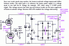
> half of the B+ voltage.
Sadly the plan has *both* B+ and B-, bipolar, notionally +/-100V, with cathodes siting near zero and B-.
> I honestly don't know what math I'm supposed to be using to calculate this...
It is "obvious"; but considering he tells you EVERYthing else, including bias for every tube in the pile, and -3dB points for various loads, but does not point out that R4 R7 drop voltage from raw B+ to final rails.... I think if you bought this, you should ask John to send the missing page or make-up an explanation.
"Obvious" (if you do this too much): the lower resistor has to be 50K or less. It has to divert cathode leakage. <50K is sufficient diversion. Inspection of cathodes at roughly +1V and -99V suggests a -50V bias. BUT John has laid-out, not from the +/-100V rails, but from the raw +/-160V rails. So assume R8 is standard-value 47K, assume -49V, work the math, R9 should be 88K. But this is NOT critical. Could be 50K or 200K and the heater-cathode voltages would be entirely safe. So pick R9=100K. Then compute power in R9 and round-up double to get a 2W power rating. R8 will dissipate about half that, so could be smaller.
The computation could be repeated for other ACV sources or DC rails other than +/-100V. But it won't get much different, except above +/-200VDC raw (160-0-160VAC) you should double-up the Watts again.
Attachments
Last edited:
"equal to one half the B minus voltage" is the correct value. (Should add Vk, but this will be small.)
But I do not think he fully thought this through. He derives separate V+/V- for each channel. But there's only one heater supply. Derive heater bias from Left? From Right? Run four 180K resistors from the four cathodes to a common heater reference point? This would be exact math average but would add crosstalk, possibly above the -40dB level.
Given one heater for two separate channel supplies, _I_ would think to take the raw -160V to zero (not +160V) and divide it by 1/3rd, make -54V. Half the dissipation also.
Thanks very much, really excellent explanation, and the notes on the schematic are very helpful. It looks like older ACF-2 Octal PCBs may not have had R8 and R9... it was a more recent addition. In this image they aren't present on the board: ACF-2 Octal Aikido Cathode Follower Kit ... that may be why they are hardly discussed in the manual, which appears to be a carry-over from the noval version.
- Status
- This old topic is closed. If you want to reopen this topic, contact a moderator using the "Report Post" button.
- Home
- Amplifiers
- Tubes / Valves
- Glassware Audio Design
