
When i tried to on the amp and gave 100hz signal I was not getting output. But there was good signal on the preamp side. I just tried to jumper and the signal came on the output. But the sine wave is slightly more towards negative side. I tried to adjust bios and nothing look like it change. I was using 2ohm current limiter. I will try to put the biard in case and try without current limiter.
I tried to set the bios without current limiter when I am turning the pot there is no change in current until almost all the pot is turned I got a slight increase in current from 0.7 to 0.8 which is strange. It have no dc on speaker terminals in when checked separate channels but on bridge it is having dc. I found two small transistors 2L one was bad i replaced with 2t and now the other 2l went bad.
Attachments
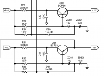
Bias pot
The header allows you to install a shunt to defeat the bias circuit when servicing. This prevents the output transistors from overheating when not clamped to the heatsink.
Dear Sir,
Can you tell me what is Q9 and Q8? I am only getting 8v across pin 4 and pin8 on u16 and u25. I feel the person messed up with Q9 and Q8.
Thank you sir. But do you know which one is 2T and which one is 2X from Q8 and Q9.2T = MMBT4403
2X = MMBT4401
Someone else should confirm this!
I'm working from information from a different amp but it appears to be similar. Q8 is designated as 4g which could be a BC860C.
https://assets.nexperia.com/documents/data-sheet/BC859_BC860.pdf
Q9 is designated as 2G which could be a BC850C.
https://assets.nexperia.com/documents/data-sheet/BC849_BC850.pdf
https://assets.nexperia.com/documents/data-sheet/BC859_BC860.pdf
Q9 is designated as 2G which could be a BC850C.
https://assets.nexperia.com/documents/data-sheet/BC849_BC850.pdf
I'm working from information from a different amp but it appears to be similar. Q8 is designated as 4g which could be a BC860C.
https://assets.nexperia.com/documents/data-sheet/BC859_BC860.pdf
Q9 is designated as 2G which could be a BC850C.
https://assets.nexperia.com/documents/data-sheet/BC849_BC850.pdf
I have changed the transistors to correct transistors now the amplifier is going into protect. Pin 16 of tl494 is having 10v. All the outputs and resistors seems to be good. Can I get a schematic for the similar type amplifier or a help in this matter. Thank you.
There are diagrams that are given to me that I agree not to distribute. This is one of them. It's a Mosconi amp (X-ION2802) so if someone has access to mosconi diagrams, maybe they can send it to you. Have you tried emailing the manufacturer to see if they would send it to you?
There are diagrams that are given to me that I agree not to distribute. This is one of them. It's a Mosconi amp (X-ION2802) so if someone has access to mosconi diagrams, maybe they can send it to you. Have you tried emailing the manufacturer to see if they would send it to you?
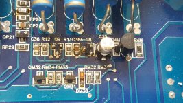
I tried by sending them email but they did not even reply to me. I removed the outputs and it is still going into protect. Can you tell me what is QM32 and QM31 and if they are in protection circuit.
Dear Sir,There are diagrams that are given to me that I agree not to distribute. This is one of them. It's a Mosconi amp (X-ION2802) so if someone has access to mosconi diagrams, maybe they can send it to you. Have you tried emailing the manufacturer to see if they would send it to you?
The amp is having 4v DC one one channel and 6v dc on another. Turning bias pots changing voltage on output terminals. But the pot is only 10k it don't have more anticlock wise rotation to reduce voltage to 0.
There are diagrams that are given to me that I agree not to distribute. This is one of them. It's a Mosconi amp (X-ION2802) so if someone has access to mosconi diagrams, maybe they can send it to you. Have you tried emailing the manufacturer to see if they would send it to you?
Dear Sir,
I have figured out why it is going into protect. One of the traces that coming from over current sense transistor was grounding. I connected direct wire and the amp coming on very good. But as I on the amp there is boop sound on speaker and while I off also I am getting sound. That means mute circuit is bad. But I have checked all the parts and I did not find any bad components. Also it don't have much power. As I increase sound it goes to protect. And bias has no affect on emitter resistors. The ideal voltage across the resistor is 0 and some resistors 0.1 to 0.2mv. I need tour help.
- Status
- This old topic is closed. If you want to reopen this topic, contact a moderator using the "Report Post" button.
- Home
- General Interest
- Car Audio
- gladen xl275c2