After injecting a signal I found the signal unaltered on the scope exiting the preamp board. So I started looking on the amp board, there I found bias trans Q13 with one leg basically un-soldered (previous tech). I also took the opportunity to replace C7 & C14 220uF/63V lytics and D5,6,11,12 on the supply rails. The results were good - no more distortion (so far) running into either 8 or 4 ohms, on either the 300W amp or the 100W amp. Bias is solid on both amps but I didn't like the ease in which the R38 bias pot moved, and thought that it might be possible that the resistor/bias is being affected (vibrating/moving) at certain frequencies with the head sitting on top of 15 and 2x10 cabs. So I'll check the bias again in a few days and see, but for now all is well....again. I'll post again if anything changes.
Well, something has changed. After playing the 800RB for a little while it was obvious that there was something amiss.
I kept getting a crackling kind of artifact that showed up about 15 min from power up. I know it's not the speakers, as I tried other heads without problem. As a recap of what was done earlier in this thread - I all but completely rebuilt the power supply board and it's working fine. On the amp board I previously replaced C7/C14 (220uF /100V) electrolytics and all of the diodes. The bias was set pretty accurately although the R38 trim resistor seemed a bit "touchy" for my liking. So this is where my current ailment begins. Because of the crackling problem I decided to pull and check all of the original Moto MJ15022/23 and measure them. The Q8/Q10 pair of 15022/23 in the 100W amp section measured way low and the others were all over the place - so I decided on a fresh set for the entire amp, including the MJE15030/31 drivers for the 100W amp section and all of the small signal transistors. This is where my brain went south for the summer. During the install I switched Q2 (MJE15031-PNP) with Q7 (MJE15030-NPN). Eminently sure I hadn't made any mistakes with the substitutions, I powered up the amp (..yes, at line voltage) and, for a second, R25 (0.33 Ohm) lit up like Granny's bathroom night light!
I powered down immediately. Since then I've checked pretty much every component on the PS and amp boards, including pulling and measuring all of the newly installed TO-3's. Luckily none were damaged. It doesn't even seem that R25 was damaged either as it measures 0.5 Ohm just like all the others. After testing and finding Q2/Q7 still measuring fine I reinstalled them correctly and, of course, powered up on the DBT - which lit up brightly. So there seems to be a problem somewhere... duh. The first thing I did was separate the PS from the amp board and test voltages there. All supply voltages including the +/- 15V supply are spot on. It seems the problem is indeed on the amp board. So my questions are:
1. Is it possible to reconnect / isolate this amp board "in sections" i.e. connect the +60V / -60V - 100W amp rails (..with or without the 15V supply) by itself and then, if there is no excess current draw, connect the +85V / -85V amp rails in an attempt to isolate the section where the problem might be? Or just reconnect the entire amp board and voltage check on the DBT? Even though both sections have different supplies they share the ground - which makes me think that reconnecting it in "sections" might not be possible for troubleshooting. But it's a question I needed to ask. Which brings me to question 2.
2. If I do reconnect all of the supplies to the amp board again can I leave this particular amp running on the (100W) DBT while I prod about for voltages without worrying about anything going up on smoke? (..there are no other component mistakes ; )
I have to admit I've gotten a little "gun shy" after fearing earlier that I might have just toasted 11 new T0-3's, Luckily that didn't happen, but it did cause me to re-assess ways I might troubleshoot this amp. I've re-posted the associated docs here again in hope for any input and insight into my current situation and questions. I refuse to give up on this amp. When working it's quite nice and I'm thinking of making it my main squeeze. So any input is greatly appreciated,
Thanks!
Note: In the service manual below, my amp board is 406-0044C version and the PS board is the 206-0048C version, found on pages 17/18.
Attachments
Update - 8/29/23:
Even though I pulled all of the T0-3 outputs, and they all tested good, Q10 has apparently given up the ghost.
I used one of the original, higher hFE Motos to confirm that this was the problem. I've got another set of MJ15022/23 to replace Q8, Q10 (again) and hopefully all will be well. More to follow..
Well, since I last checked in I've replaced Q10 on the amp board that had previously tested good but later failed. So all of the TO-3 output transistors are new and working. The amp powers up on the DBT and the light dims. R25, that had previously lit up like a light bulb when I accidentally swapped Q2 & Q7 (..see earlier post) has been replaced as well. The bias settles in at 5mV on both channels just fine. What I thought was a problem I now don't think actually is, because, with no load on the amp at shut down there is a straight -37vdc headed straight out of the output (speaker) jack. As I understand it - all DC headed toward a speaker is bad news - but with an 8 Ohm dummy load on the amp the voltage at shut down never drops below about 150mV. Not a problem in my book so I'm calling this done. It's dialed in pretty well and there may be one or two updates still down the road but it sounds great and is working fine. thanks again to @epicyclic, @tikiroo, @BSST and @Ganthercage for all the help and input with this amp. I'm calling this thread closed with best wishes to all of you!
I am also checking out a 800RB the owner says the 300W section doesn't work but the 100W does. The unit turns on just fine, i.e. doesn't blow the fuse and doesn't smoke! 🙂
At first I thought nothing was wrong with the unit, but with feeding an audio signal to the input and listening to the 300W output, after about 4 minutes the the volume drops very low. The output is going to a 8 ohm speaker.
Does this make sense on how the Biamp button works?
With a speaker plugged into the 300W output, when the button is out (Full biamp) the 100W volume dial does nothing and the 300W controls the volume. With the Biamp button pushed in sounds like just bass is coming out of the speaker.
With the speaker plugged into the 100W output the 100W volume dial works just fine regardless of the biamp button, and the 300W volume control does nothing. In this configuration the Frequency dial does change the tone.
Circuit boards are:
Power supply: 206-0048-C9
Power amp: 206-0044-C8
Pre-amp: 206-0045-E
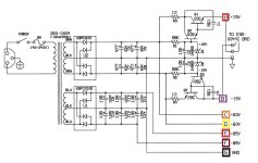
The main rails are supposed to be +/- 85VDC but I'm only getting 75VDC, is this close enough? +/-15 supplies look good.
I'm not sure if I have the right schematics but collectors (case) of Q21,22,23,24 all read -75.5VDC, Q17,18,19,20 all read +75.7 VDC. Q12 collector +1.15VDC. Q8 +59.4, Q10 -59.4VDC. All these transistors are either MJ15022 (NPN) or MJ15023 (PNP).
At first I thought nothing was wrong with the unit, but with feeding an audio signal to the input and listening to the 300W output, after about 4 minutes the the volume drops very low. The output is going to a 8 ohm speaker.
Does this make sense on how the Biamp button works?
With a speaker plugged into the 300W output, when the button is out (Full biamp) the 100W volume dial does nothing and the 300W controls the volume. With the Biamp button pushed in sounds like just bass is coming out of the speaker.
With the speaker plugged into the 100W output the 100W volume dial works just fine regardless of the biamp button, and the 300W volume control does nothing. In this configuration the Frequency dial does change the tone.
Circuit boards are:
Power supply: 206-0048-C9
Power amp: 206-0044-C8
Pre-amp: 206-0045-E
The main rails are supposed to be +/- 85VDC but I'm only getting 75VDC, is this close enough? +/-15 supplies look good.
I'm not sure if I have the right schematics but collectors (case) of Q21,22,23,24 all read -75.5VDC, Q17,18,19,20 all read +75.7 VDC. Q12 collector +1.15VDC. Q8 +59.4, Q10 -59.4VDC. All these transistors are either MJ15022 (NPN) or MJ15023 (PNP).

Well, a couple of things first. If you read the manual it suggests that you run the amp with the 100W and 300W master volumes at "full" - and use the "Volume" knob (far left) to control the output. Weird yes? Anyway...that's what they say and that's what I've been doing since I got mine running correctly. As for the Biamp button "Full". is button out and "Biamp" is button in. Your B+ voltages are fine - mine were almost exactly the same and your +/- 15V is good so the "problem" must be somewhere else. If you read my thread here you'd see I had various issues to deal with. Long story short - I ended up replacing a lot of stuff just because it's an old amp and I wanted to be sure it was solid in the end. It seems like you've checked your power supply voltages so if you're running a single 8 ohm cab from the 300W output and you're not getting decent volume try setting the controls as I mentioned above and see what you get. If you don't already have the service and or user manual - get them. I've uploaded the service manual below. All amp voltages are on the schematic but make sure that you're looking at the correct amp schematic for the power supply, amp and preamp boards that you have. They're listed on the bottom of each of the schematic diagrams in the service manual. I'll check back later and see what you've found.
Attachments
Sounds great. You still might want to check the DC offset at the 300W and 100W outputs. I use a 1/4" in. plug with two wires soldered to the leads - or you could just clip your meter to the jacks inside. But be careful any time you're inside an amp that's turned on. If you aren't sure or experienced with stuff like that make the plug and measure from outside of the amp. I'm glad it wasn't a serious problem 'cuz measuring the bias and some other points can be a real pain with this amp.
Best of luck to you and remember to run the amp the way they recommend in the manual - with the masters at (or close to) full, and adjust your output volume with the "Volume" knob on the far left of the face-plate. You'll get better sound quality by far.
M
Best of luck to you and remember to run the amp the way they recommend in the manual - with the masters at (or close to) full, and adjust your output volume with the "Volume" knob on the far left of the face-plate. You'll get better sound quality by far.
M
- Home
- Amplifiers
- Solid State
- GK 800RB Help request! (..yes, another one ; )