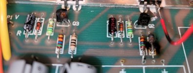
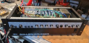
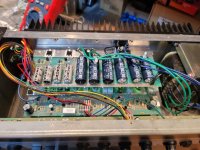
Greetings, I received a GK 800rb from a friend recently and although I've repaired a number of solid state bass amps, I've got questions about this one. When I received and opened it, and looked at the power supply board it was obvious something odd was going on. The PS board is the 206-0048-C version - and R3 (10 Ohm) was toast (see pic), also Q3 (MPSA56) had it's face blown off and Q2 (MPSA06) was inoperative.
I pulled and checked every component on the power supply board except the six 1000 uF/100V filter caps.
R1 & R2 (56K Ohm) tested spot on,
C1 & C4, C2 & C3 all tested fine.
I pulled and tested rectifiers KBPC603 & KBPC 2502 and they tested fine.
I pulled and tested the four C5 - C7 (470uF/63V) caps and all tested good.
I replaced the burnt R3 and it's pair R4 (10 Ohm)
I replaced the defective Q2 & Q3 pair (MPSA06/MPSA56)
I also replaced 16V Zener diodes D1 & D2 with new and also replaced Q1 & Q4 (TIP31c - [B.C.E.] installed) because of what I saw when I opened this amp.
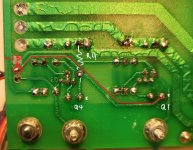
In the pics submitted you can see where someone had attached the -15V (Red) supply wire directly to the emitter of Q4! And even more odd was that when I looked at the underside of the PS board, where the -15V wire is labeled on top of the board to go, it doesn't look like anything had ever been soldered there! After checking the schematic and looking at pics of other 800RBs I decided to put it where "it's supposed to go".
It's at this point where I could use some advice (at least)...
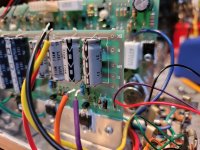
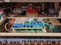
Having read possibly all of the GK800RB threads here on DIY I decided it was probably prudent to isolate the PS aboard before troubleshooting further. My question is this - as you can see in the pics I've disconnected all of the PS feeds to the amp board: Y/Or/P*/R/Bk (*the board says brown but it's purple on mine) and the Red -15V and the purple +15V supply wires with the molex plug is hanging off the side. Note: the black ground wire in the disconnected +/- 15V supply plug is still connected to one of the output jack sleeve/chassis connections (and I'm not sure if it should remain there during isolation tests)
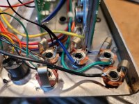
Question: Is it correct that the Black wire on the board (the two secondary center taps) be disconnected also? Or should the Black wire be left in place to provide the ground when the amp while testing? And if this is the case, and it should be left in the PS board, does the entire rear of the amp actually need to be placed (screwed) back in the amp chassis during testing? Note: the other end of the black wire is connected to one of the output jack's sleeve/chassis connections also.
So, it's a "what's the correct way to isolate the PS for testing the PS board in the 800RB?" question. I've added the other info to illustrate my reasons for doing what I've done so far and the questions swirling around in my head currently.
Well, that's where I am right now. I'm awaiting further instruction in the troubleshooting of this amp from those that know more than I do.
All assistance and insight is appreciated. Thanks
Mark
I pulled and checked every component on the power supply board except the six 1000 uF/100V filter caps.
R1 & R2 (56K Ohm) tested spot on,
C1 & C4, C2 & C3 all tested fine.
I pulled and tested rectifiers KBPC603 & KBPC 2502 and they tested fine.
I pulled and tested the four C5 - C7 (470uF/63V) caps and all tested good.
I replaced the burnt R3 and it's pair R4 (10 Ohm)
I replaced the defective Q2 & Q3 pair (MPSA06/MPSA56)
I also replaced 16V Zener diodes D1 & D2 with new and also replaced Q1 & Q4 (TIP31c - [B.C.E.] installed) because of what I saw when I opened this amp.
In the pics submitted you can see where someone had attached the -15V (Red) supply wire directly to the emitter of Q4! And even more odd was that when I looked at the underside of the PS board, where the -15V wire is labeled on top of the board to go, it doesn't look like anything had ever been soldered there! After checking the schematic and looking at pics of other 800RBs I decided to put it where "it's supposed to go".
It's at this point where I could use some advice (at least)...
Having read possibly all of the GK800RB threads here on DIY I decided it was probably prudent to isolate the PS aboard before troubleshooting further. My question is this - as you can see in the pics I've disconnected all of the PS feeds to the amp board: Y/Or/P*/R/Bk (*the board says brown but it's purple on mine) and the Red -15V and the purple +15V supply wires with the molex plug is hanging off the side. Note: the black ground wire in the disconnected +/- 15V supply plug is still connected to one of the output jack sleeve/chassis connections (and I'm not sure if it should remain there during isolation tests)
Question: Is it correct that the Black wire on the board (the two secondary center taps) be disconnected also? Or should the Black wire be left in place to provide the ground when the amp while testing? And if this is the case, and it should be left in the PS board, does the entire rear of the amp actually need to be placed (screwed) back in the amp chassis during testing? Note: the other end of the black wire is connected to one of the output jack's sleeve/chassis connections also.
So, it's a "what's the correct way to isolate the PS for testing the PS board in the 800RB?" question. I've added the other info to illustrate my reasons for doing what I've done so far and the questions swirling around in my head currently.
Well, that's where I am right now. I'm awaiting further instruction in the troubleshooting of this amp from those that know more than I do.
All assistance and insight is appreciated. Thanks
Mark
Attachments

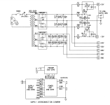
Yup, not only did I list the part number incorrectly above, I forgot to upload a copy of the PS board schematic in question for convenience.
Thanks, ... I appreciate the copy. I understand the logic in separating sections of an amp for troubleshooting purposes I just haven't had to do it very often to repair the things I have repaired. I'm not really into destroying the things I work on so I thought it better to ask in this case than "experiment"! : )
[ GK 800RB Power supply board 406-0048-C ]
Attachments
Last edited:
The photo shows the red wire soldered to the emitter of Q1, which is correct assuming red is positive (like it usually is....)
Edit: The schematic shows violet -15, red +15
Edit: The schematic shows violet -15, red +15
Erring on the side of safety the centre taps should have an electrical path to chassis and the chassis have a path to the safety earth , to cover the highly unlikely event that the transformer is faulty and putting out mains voltage on the secondaries .
The 15V outputs will need loading with say 1K5 ohms to get them to regulate as they are the simple non feedback type .
The 15V outputs will need loading with say 1K5 ohms to get them to regulate as they are the simple non feedback type .
The photo shows the red wire soldered to the emitter of Q1, which is correct assuming red is positive (like it usually is....)
Edit: The schematic shows violet -15, red +15
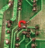
I think I found a problem: If you look at the annotated picture I've highlighted in red the +15V (red) circuit path - current goes right from the emitter of Q1 to R4 and the emitter of Q4, which are both connected to the -60V rail. I think this is a mis-drill, and that's why the direct connection to the emitter of Q1 that was present when I opened this up. A solution for sure, but not very pretty. I pulled the end of R4 so you could see where the solder pad is mis-connected directly on top of the +15 circuit trace. Is this assessment correct?
Attachments
Last edited:
Thanks, "epicyclic" I'll hook the black wire back before I re-test the PS board. So... a 1K5R should be placed in the molex plug between the +15V and -15V connections?Erring on the side of safety the centre taps should have an electrical path to chassis and the chassis have a path to the safety earth , to cover the highly unlikely event that the transformer is faulty and putting out mains voltage on the secondaries . The 15V outputs will need loading with say 1K5 ohms to get them to regulate as they are the simple non feedback type .
Seems that way, not a mis-drill but a layout error. I assume the trace from Q1 emitter has been cut so that it doesn't actually join to the R4/Q4 emitter junction? It looks like it has, but maybe you should scrape some more of the trace off to avoid any accidental connection. Also cut the trace from that junction to the original +15V connection point.I think I found a problem: If you look at the annotated picture I've highlighted in red the +15V (red) circuit path - current goes right from the emitter of Q1 to R4 and the emitter of Q4, which are both connected to the -60V rail. I think this is a mis-drill, and that's why the direct connection to the emitter of Q1 that was present when I opened this up. A solution for sure, but not very pretty. I pulled the end of R4 so you could see where the solder pad is mis-connected directly on top of the +15 circuit trace. Is this assessment correct?
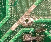
Definitely a layout error, as the R4 solder pad is actually part of the +15V trace. Or at least it was 😉 I've added pics of the way I disconnected R4 from the +15V circuit trace and place a jumper there so I wouldn't have to do the "wire direct to Q1 emitter" kluge. After this was done I applied "epicyclic's" suggestion and placed a 1.5K resistor from the + & - 15V tap to ground for circuit load, reconnected the black ground lead to the PS board and lit her up. And thankfully the DBT lit and went dim. With the PS isolated the amp only drew 213mA. OK,.. So my supply voltages were:Seems that way, not a mis-drill but a layout error. I assume the trace from Q1 emitter has been cut so that it doesn't actually join to the R4/Q4 emitter junction? It looks like it has, but maybe you should scrape some more of the trace off to avoid any accidental connection. Also cut the trace from that junction to the original +15V connection point.
+58.7 [+60V] [schematic]
-58.7 [-60V]
-74.7 [-80V]
+74.6 [+80V]
The 15V circuit measured:
+14.6V [+15V]
-15.4V [-15V]
Not bad. I then reconnected the rest of the power amp board leads and the 15V supply to the PS board alone, powered it up - the DBT lit and dimmed - current draw was only 245mA. At this point I reconnected the rear of the amp back to the main cabinet - connected the three preamp plugs - and powered up. The DBT lit and dimmed again. Current draw was only 269mA. I feel a lot better now (sigh of relief~) I'll be stopping here for tonight and take a look at more voltages and the bias tomorrow. I've read several different posts about biasing this amp and I'll go back and read them again. If I remember correctly the methods mentioned here by several folks were a bit less involved than the version in the schematic. But either way I'll check the bias before running audio through. All suggestions and comments are, of course, still welcome. We're not home until I'm rockin' this puppy through my Bag End D10XD 2x10 and JBL 4625b cabs...at the same time! : )
Thanks much, tikiroo and epicyclic for your kind assistance with this amp so far. I'll be back at it tomorrow.
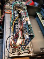
The pics below show how I disconnected the R4 pad from the +15V circuit trace and jumped it.
Attachments
...or would that be 1K5R from each 15V port in the molex connection to ground?
This option .
An update and a question:
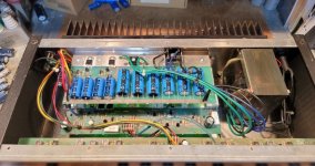
After I fixed the circuit trace that was laid out with R3's (+60V) eyelet right on top of Q4's Emitter supply (-60V) the amp stopped drawing excessive current and came off of the DBT. My supply voltages were a little low so I decided to recap the PS board (pics below). After that the supply voltages went from +/- 58V to +/-60V and from +/- 74V to +/- 78V respectively; the +/- 15V supply stayed the same. With no load and no input the amp settles in at 238mA, within a few seconds, off of the DBT.
On the 406-0044c amp schematic (pic 2) there is a "simplified" procedure for setting the bias on the 100W and 300W amps.
I followed this procedure and it dialed right in - solid and stable. DC offset for the 100W amp after about 10 min is: +/- 0.0002V and the 300W amp is -0.015V. I also checked all of the voltage points provided on the amp schematic - all green.
This is when I decided to give it a listen - it's nice and quite and the little power-on bump is there with this unit as well, but no big deal at all. What concerns me is that when I hooked it up to a JBL 4625 cab with an E140-8 driver in it, the driver would start to distort after about a minute or so. It's old so I thought maybe it's just the driver. I have a few 15's around so I threw in an Eden EC1503XL and the same thing happened. It's rather old also so I grabbed a very seldomly used JBL 2226H and the same thing. So I'm guessing that it's probably not the drivers - even though they do have differences compared to the original E140-8. But when not being driven hard at all I don't think they should ALL be distorting.
So I think I may be in for a bit more troubleshooting of the 800rb. I think I saw other 800rb threads, here or elsewhere, where at least one other person was having similar issues. I'll go back and try to find that. And I guess having a look at the preamp may be on the menu as well. If anyone has any input I'd appreciate hearing since possible causes for this aren't readily apparent to me. Thanks for tuning in,
M
Attachments
Last edited:
...one more thing. I also played the JBL cab using an Eden WT300 head and no distortion from the JBL 2226H. So I think it's probably the 800rb. Furthur...!
That did it, epi! Another case of user error. "RTFM".. I always tell my friends. Looks like what's good for the goose is good for the tech! I guess starting with the "master" output volumes low and pre volumes high, like I think most are apt to do, results in some sort of imbalance between the pre amp and power amp. I got no distortion at all now and it sounds noticeably better. Thanks much, I appreciate you helping with this amp repair all the way through. For now I think I'm good. I"ll play it a while and see what I get. Take care and see ya around the forum.
Mark
Mark
Of course,.. I spoke too soon and jinxed myself, I think. It's doing it again. 😖 I put a jumper in the send/return jacks and that's not the cause. Both 100W & 300W "masters" at at full and the boost and pre volume are started out low - and this time the distortion is starting out immediately. There is a preamp voltage test procedure that's outlined in the service manual but it calls for "2mA" input to illicit the displayed voltages. I've got a BK Precision 4003 signal generator but it won't create a proper sign wave below about 150mA, even with the -20dB pad initiated. So I'm back at the bench trying to figure out the best way to troubleshoot this thing. Also: I noticed that when this amp is shut off there is a negative voltage that comes out of the output to the tune of about -34V, and then slowly drops from there.
I can't see this a necessarily normal, but there is a lot about this amp that's counter intuitive. All input appreciated...
I can't see this a necessarily normal, but there is a lot about this amp that's counter intuitive. All input appreciated...
Thanks for the input. I realized this about the ground wire mentioned above a while ago when I was working on the power supply. Right now I'm trying to figure out why I'm getting distortion while playing. I thought I had it licked after reading the sound setup section of the service manual - I hooked up both the 100W and 300W amps to an 8 Ohm and 4 Ohm cab, respectively, and all went well. No distortion, no probs, great sound.
But when I ran just the 4 Ohm cab with the 300W amp I got the distortion immediately. I know you can't do 4 Ohm with the 100W tap but the 300W amp should do it fine, I believe. So right now I'm at a loss, but forging forward.
But when I ran just the 4 Ohm cab with the 300W amp I got the distortion immediately. I know you can't do 4 Ohm with the 100W tap but the 300W amp should do it fine, I believe. So right now I'm at a loss, but forging forward.
There is a preamp voltage test procedure that's outlined in the service manual but it calls for "2mA" input to illicit the displayed voltages. I've got a BK Precision 4003 signal generator but it won't create a proper sign wave below about 150mA, even with the -20dB pad initiated.
Use an additional potentiometer as a voltage divider to lower the level .
Send a signal from the BK directly into the effects return to check the power amps / electronic crossover ( dependant on switch position ) in isolation .
Last edited:
- Home
- Amplifiers
- Solid State
- GK 800RB Help request! (..yes, another one ; )