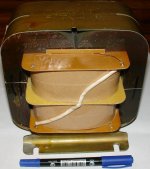
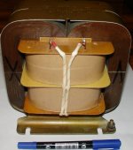
The OPT is a split bobbin design (two bobbins), wire of the primary is 0,5mm (including insulation), wire of the secondary is 1,1mm. Primary's sectioning is 4-8-8-4, secondary's is 2-2-2. Iron core 40cm2.Very nice work 🙂
Give us some info regarding the OPT's used in this project
Chris
All primary's sections are consequent, all secondary's sections are in parallel.
Resulting number of wounds per bobbin is 1838 and 74. For two bobbins (whole trafo) is n1=3676 and n2=74. I used such trafo with both GM70 and GK71. The aim was lower output impedance and lower distorsions.
With GM70 output impedance (1kHz) near 0,8 Ohms, with GK71 near 0,65 Ohms.
Very nice work, has anyone made sound comparisons G3 on ground vs. G3 connected to plate. I always connected g3 to plate and experienced higher possible dissipation and got up to 65W output power at 1050Volts plate-ground at 6kOhms load. Does the GK71 sound really better with g3 on ground. And: at whats the highest acceptable plate voltage?
Greetings from Germany and have a look at my 800W monster amp:
http://www.stadtbahnfreund-h.de/misc/impact800.jpg
Greetings from Germany and have a look at my 800W monster amp:
http://www.stadtbahnfreund-h.de/misc/impact800.jpg
Now this amp is in the system of my friend, and he has achieved excellent sound with Yamaha Soavo I speakers and Ortofon interstage and speaker cables (two pairs, bi-wiring). 3d stage and details are excellent.
I did not try connecting g3 to plate, some pentodes become unstable if g3 not on the ground. Therefore I afraid of some even low-level oscillations if g3 is on plate.
I wish you success in the efforts with high power designs.
I did not try connecting g3 to plate, some pentodes become unstable if g3 not on the ground. Therefore I afraid of some even low-level oscillations if g3 is on plate.
I wish you success in the efforts with high power designs.
With that huge core area and careful OPT engineering, I suspect this amplifier can kick some serious butt. Congratulations for your design!
I'm curious. What is you g2 voltage and does it handle it well?
Have you measured the leakage inductance of your OPT? Do you mind sharing?
I'm curious. What is you g2 voltage and does it handle it well?
Have you measured the leakage inductance of your OPT? Do you mind sharing?
I use gk71 in triode connection, separate g2 voltage is not needed. Compared to graphite plate gm70, triode connected gk71 seems to be better. But copper plate gm70 is more "delicate", however they could not achieve the same bass as with gk71 in triode.
At the same time, one must remember, that among the same tubes family there is a wide raw of various manufacturers, plate and grid materials, structural features. There could be graphite gm70 (by Foton), that is better than Ulyanovsk gk71 (year 1990). I still have a matched pair of Foton gk71, that must produce very respectful sound. One must not think, that all soviet tubes are crap. If they are cheap, than most probably they do. But there are also very good soviet tubes versions, and they are close to western good tubes pricewise.
Regarding the leakage inductance of this kind of OPT, I could measure it, and inform about the value obtained, since I have a pair of these trafos, prepared for next project.
Last edited:
Yes, but in triode connection G2 is tied to the anode. What is the maximum voltage it can withstand, ignoring the mentioned datasheet value?
I'm asking this, because I'm planning to build a SET in the GM70 range.
Thank you for your reply.
I'm asking this, because I'm planning to build a SET in the GM70 range.
Thank you for your reply.
Datasheet g2 voltage is mentioned for pentode conection. In triode mode, nobody reported about any problem regarding g2 voltage limitation, even in above-1kV range.
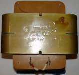
Here are some pictures and measurements of the output transformer.
With secondary shorted,
- primary's inductance reading is Ls = 14mH
- capacitance between primary and secondary is 8,66nF
Active resistance is 113 Ohms (primary) and 0,1 Ohms (secondary)
Inductance of primary is near 90H
Formular for high frequency cutoff
Fh(kHz)=(Ri+Ra)(Ohms)/(6,28*Ls(H)) = (1200+10000)/(6,28*0,014) = 127kHz
Attachments
Last edited:
If you wish, you can try my measurement method. I'm pasting it from another topic.
Nice work on your transformer by the way.
Then, by finding Cp, you can easily calculate Ls.A not entirely, but more realistic method of measuring parasitic parameters is to load the secondary, then add a capacitor with a small (10-20nF) value shunting the primary. Then measure the first resonant frequency across the primary. Then measure it again without the capacitor. The later should be the default first resonance and higher than the one with the shunt capacitor
The added capacitor is practically in parallel with the Cp (shunt capacitance), so the resonant frequency will be lowered. To find Cp:
Cp = Cadd / [(Fres1/Fres2)^2 - 1]
Fres1 is the frequency without Cadd
Fres2 is the frequency with Cadd
Nice work on your transformer by the way.
Last edited:
In this measurement approach, should we think about output impedace of sine signal generator?If you wish, you can try my measurement method. I'm pasting it from another topic.
Then, by finding Cp, you can easily calculate Ls.
Nice work on your transformer by the way.
Also please add the formula you use to calculate Ls from Cp.
I'm using a 1k resistor and a true RMS voltmeter on the secondary.
fres = 1 / 2*pi*sqrtLC
So, Ls = 1 / (2*pi*f)^2*C
fres = 1 / 2*pi*sqrtLC
So, Ls = 1 / (2*pi*f)^2*C
For 50W output you need a SE150B C-Core at least. But from my experience internal winding capacity is limiting the frequency range. Copper wire will not be sufficient.Here are some pictures and measurements of the output transformer.
With secondary shorted,
- primary's inductance reading is Ls = 14mH
- capacitance between primary and secondary is 8,66nF
Active resistance is 113 Ohms (primary) and 0,1 Ohms (secondary)
Inductance of primary is near 90H
Formular for high frequency cutoff
Fh(kHz)=(Ri+Ra)(Ohms)/(6,28*Ls(H)) = (1200+10000)/(6,28*0,014) = 127kHz
For 50W output you need a SE150B C-Core at least. But from my experience internal winding capacity is limiting the frequency range. Copper wire will not be sufficient.
Split bobbins approach must be used for decreasing dynamic internal winding capacity. I used two bobbins, somebody from Greece I remember used four split bobbins.
What do you mean about copper wire not sufficient? I think silver is not feasible.
This will not help with decreasing internal winding capacity, but could decrease active resistances of windings.
It can significantly help decreasing primary to secondary capacitance in case the secondary is grounded. Hint - think of the spreading of the voltage potentials between the primary and secondary, and the secondary layers connected in series. A good compromise solution - two secondary parallel blocks connected in series and the resulting center tap grounded instead of one end. Hint2 - check N. Crowhurst's papers.
Primary to secondary capacitance is another story. For handling this issue, one should not use excessive sectioning of windings, gold middle is to be taken. Also, with some limitations, grounding of secondary via substantial value resistor could be used (in diy designs this can be admitted).
The dynamic internal primary winding capacity is created due to the voltage appearing between adjacent (top-bottom) wounds, and this voltage is decreased by split bobbin solution, square wire would not help in this, on contrary, it would increase internnal capacity due to geometry factor.
The dynamic internal primary winding capacity is created due to the voltage appearing between adjacent (top-bottom) wounds, and this voltage is decreased by split bobbin solution, square wire would not help in this, on contrary, it would increase internnal capacity due to geometry factor.
Last edited:
Yes, I'm only talking about primary to secondary capacitance here.
The idea behind the square wire (or multifiliar secondary layer) was to make the connection of secondary layers in series possible, thus minimizing the potential differences between primary and secondary layers, in the end minimizing this capacitance.
A squared conductor will hurt primary to primary clumped capacitance. To reduce the clumped capacitance, the best method I know is to employ vertical sectioning. Or bank-winding if you're a hardcore winder. I dare not. 😀 By doing a split-bobbin design, you did a small successful version of vertical sectioning.
Silver wire is necessary from my experience. Or bifilar wiring.Split bobbins approach must be used for decreasing dynamic internal winding capacity. I used two bobbins, somebody from Greece I remember used four split bobbins.
What do you mean about copper wire not sufficient? I think silver is not feasible.
- Status
- Not open for further replies.
- Home
- Amplifiers
- Tubes / Valves
- GK-71 SE amp