Hello,
I have finaly build amplifier with STK442-090.
I build it on prefboard but I did my best to make it as best as possible.
The problem is that im getting -31vdc out of both speaker outputs...
I have checked everything. But I can't find any error.
I'm getting +-31v out of psu to the board, both rails have power.
What should I check, measure?
Sub gnd should be connected to gnd rail right?
Help me please
Attachments
Hi, have you any more information on the chip than this? HTTP 301 This page has been moved
How have you mounted it, is the mounting bracket metal and is it isolated from the Power rails?
How have you mounted it, is the mounting bracket metal and is it isolated from the Power rails?
Hi, have you any more information on the chip than this? HTTP 301 This page has been moved
How have you mounted it, is the mounting bracket metal and is it isolated from the Power rails?
Hello, the link that you posted has all the informations that I could find.
I havent mounted it yet.
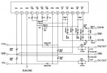
The circuit you show is the test example from Sanyo.
Check your work, make sure there is zero DC on the input lines and the feedback line GND is ground.
Hello, I will measure input lines. Which line is feedback line?
The bottom of the 1k8 resistors should go to ground through the capacitors giving AC gain to the amplifier. Gain = 56k + 1k8 / 1k8 = 57.
pins 4, 5, 6, 7, 10, 11, 13 and 14 should be close to Zero from GND.
pins 8 -ve and 9 +ve rails.
Chip datasheet; STK442-090 SANYO, STK442-090 Datasheet
pins 4, 5, 6, 7, 10, 11, 13 and 14 should be close to Zero from GND.
pins 8 -ve and 9 +ve rails.
Chip datasheet; STK442-090 SANYO, STK442-090 Datasheet
Don't run it for any length of time without a heatsink. Have you connected input and output grounds as Mark says?
I run it without heatsink just for test. I have to drill holes to the heatsink and I cant do it today. I am monotoring chips temperature all the time.
Should I connect output and input gnds together? If i measure input lines voltage across input gnd I get only few 10 of mV. But when I measure it across gnd/output gnd i get -31v so should I connect them together?
Don't worry about the voltage you are measuring there, the input ground must be connected to 0V
Ok. I will connect them together. Cant do it right now. Im not home. Will report asap when i get home.
Thank you
Don't worry about the voltage you are measuring there, the input ground must be connected to 0V
Hello,
I connected input gnd to gnd and it works
After having another look to the schematic it`s logical that it should be connected as it is writen GND next to the connection, but it wasn`t clear enought to me.Thank you very much.
It would seem to infer your initial power supply is not correct.The data sheet STK442-090 SANYO, STK442-090 Datasheet suggests to use a centretap transformer and to derive a positive and negative voltage. It also indicates 500 ohm resistors on each rail to ground. My guess is you have unequal voltages at the power supply hence the output contains an offset now indicating that error.
Check to see that you have positive voltage at Pin 1, and negative voltage at Pin 2
Check to see that you have positive voltage at Pin 1, and negative voltage at Pin 2
Good. Well, Mark spotted it first, easy to overlook. Can you see why it had the effect that it did? It provides a reference for the input and controls the feedback, without it the output floated towards the power rail
Yes, I understand a little now. But I don`t have much knowledge about details about amplifiers. This is my second big build (i dont count easy ones with only positive voltage and very few components ). First was single tube EL84 amplifier.
It would seem to infer your initial power supply is not correct.The data sheet STK442-090 SANYO, STK442-090 Datasheet suggests to use a centretap transformer and to derive a positive and negative voltage. It also indicates 500 ohm resistors on each rail to ground. My guess is you have unequal voltages at the power supply hence the output contains an offset now indicating that error.
Check to see that you have positive voltage at Pin 1, and negative voltage at Pin 2
Hello, I already fixed problem by connecting input gnd to gnd.
I have center tapped transformer, same power supply that is on the schematic, except for 2 6800uF instead of 10000uF capacitors (had the capacitors laying around and I don`t know if is necessary to use 10000uF. Sanyo stated the same psu for all stks from 15w to 200w rms).
- Status
- This old topic is closed. If you want to reopen this topic, contact a moderator using the "Report Post" button.
- Home
- Amplifiers
- Solid State
- Getting 31v on speaker outputs...