AFAIK avoiding cathode stripping is the purpose of B+ sequencing. Yet ionisation of residual gas is said to be the primary mechanism for stripping, and this seems only to be mitigated by getter performance - at least mainly.
Since a getter is unlikely to be heated to any significant extent unless anode dissipation is working, what exactly is the point of delaying B+ application in this respect ? Also timescale for getter performance is far longer than typical on/off cycle ?
Apols if this is already discussed as I feel it must have been, but a quick search didn't drop satisfying answers IMO.........
Thanks Merlinb. I get your posts on that thread, was previously unaware - I'd formed a similar opinion. In any event seems time constant for heating getter to workable temperature might never be reached in the absence of working anode dissipation perhaps, thought I'd add.
Note these facts:-
1) What is called the "getter" ie the ring or cup containg magnesium or other compounds tpically mounted on the top of the tube structure (sometimes the bottom in old style octals) and sometimes connected to the anode, is NOT what consumes the gas.
2) What consumes the gas is the "gettering", that is the silver-coloured coating on the inside of the glass inside the tube near the getter. This coating is created during manufacturer when the getter is "fired" or "flashed" by an RF induction technique. The gettering coating is pure magnesium or other chemically active metal that reacts with and fixes in place any gas molecules that come in contact with it.
3) The effectiveness of the gettering increases sharply with temperature, and thus is most effective when the glass is hot from tube operation. The increase in gas consumption is thus a slow process beginning when the equipment is switched on and may take 15 - 20 minutes or more.
4) Gas inside tubes comes mainly from electron bombardment and consequent iron bombardment of tube internal structures and is a very slow process.
Thus you can see that delaying B+ until heater are warm, which takes 10-15 seconds, has no bearing on dealing with gas.
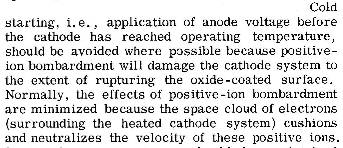
However, until the cathode is hot, the density of the electron cloud around the cathode is low, and this will let through ions caused by the limited number of electrons accelerated to the anode if the anode already has B+ applied. Therefore the cathode can be poisoned by ion bombardment by allowing the heater to warm up while B+ is already present.
The question is yes, it happens, but does it mattter? When tube rectifiers were the only thing used, it happend that the rectifier filament was heavier that the heaters of all other tubes, and sincee the rectifier cannot raise B+ until it is hot, ion bombardment of cathodes was a non-issue, except for the rectifier itself, which was under heavy stress for other reasons.
However, from about 1961 or so, manufacturers of consumer tube-based equipment (TV's & stereos) changed to silicon rectifiers, which of course raise B+ instantly upon switch on. No reduction in tube life was found to occur. Presumably becuase the number of switch-on cycles compared to total tube operating hours was typically such that cathode poisoning was a minor factor compared to the slow loss of emission due to cathode metal depletion, a continuous process that goes on whilever the cathode is hot.
"Modern" cathode coatings, ie those made after WW2, ae more robust anyway.
1) What is called the "getter" ie the ring or cup containg magnesium or other compounds tpically mounted on the top of the tube structure (sometimes the bottom in old style octals) and sometimes connected to the anode, is NOT what consumes the gas.
2) What consumes the gas is the "gettering", that is the silver-coloured coating on the inside of the glass inside the tube near the getter. This coating is created during manufacturer when the getter is "fired" or "flashed" by an RF induction technique. The gettering coating is pure magnesium or other chemically active metal that reacts with and fixes in place any gas molecules that come in contact with it.
3) The effectiveness of the gettering increases sharply with temperature, and thus is most effective when the glass is hot from tube operation. The increase in gas consumption is thus a slow process beginning when the equipment is switched on and may take 15 - 20 minutes or more.
4) Gas inside tubes comes mainly from electron bombardment and consequent iron bombardment of tube internal structures and is a very slow process.
Thus you can see that delaying B+ until heater are warm, which takes 10-15 seconds, has no bearing on dealing with gas.
However, until the cathode is hot, the density of the electron cloud around the cathode is low, and this will let through ions caused by the limited number of electrons accelerated to the anode if the anode already has B+ applied. Therefore the cathode can be poisoned by ion bombardment by allowing the heater to warm up while B+ is already present.
The question is yes, it happens, but does it mattter? When tube rectifiers were the only thing used, it happend that the rectifier filament was heavier that the heaters of all other tubes, and sincee the rectifier cannot raise B+ until it is hot, ion bombardment of cathodes was a non-issue, except for the rectifier itself, which was under heavy stress for other reasons.
However, from about 1961 or so, manufacturers of consumer tube-based equipment (TV's & stereos) changed to silicon rectifiers, which of course raise B+ instantly upon switch on. No reduction in tube life was found to occur. Presumably becuase the number of switch-on cycles compared to total tube operating hours was typically such that cathode poisoning was a minor factor compared to the slow loss of emission due to cathode metal depletion, a continuous process that goes on whilever the cathode is hot.
"Modern" cathode coatings, ie those made after WW2, ae more robust anyway.
Last edited:
An easy going but excellent introduction to getters can be found in RCA (1963) Electron Tube Design, p519 onwards.
Technical books online
Technical books online
An easy going but excellent introduction to getters can be found in RCA (1963) Electron Tube Design, p519 onwards.
Technical books online
Page 67:
Attachments
Can you double check that page number? I don't see that quote.Page 67:
It's on page 67 in this edition: https://archive.org/details/ElectronTubeDesign
In another PDF it's on page 59.
In another PDF it's on page 59.
Attachments

If the cathode is too cool to emit many electrons then there can't be very many positive ions. There is a brief danger period during warm-up when the current flow is temperature-limited - so for a few seconds the cathode is vulnerable.
The alternative, delaying HT/B+, creates a different problem: cathode interface layer. This happens when a valve has a hot cathode but no anode current. Valves designed for computer service or other intermittent operation have special cathode materials to avoid this, but most do not.
So we have a choice: cathode bombardment for a few seconds, or formation of a cathode interface layer. If the valve has a good vacuum then there is nothing to bombard the cathode with.
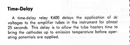
Well, Tektronix chose to preheat, in their instruments.
If in doubt, one could do worse than follow such masters.
Crash-starting may also lead to excess grid current, or grid emission. This may not be of any account for vanity amplifiers, but is not desirable if highest quality is aimed for, in amplifiers as well as oscilloscopes.
Extract from the Tek 551 manual:
Attachments
Well, Tektronix chose to preheat, in their instruments.
If in doubt, one could do worse than follow such masters.
Crash-starting may also lead to excess grid current, or grid emission. This may not be of any account for vanity amplifiers, but is not desirable if highest quality is aimed for, in amplifiers as well as oscilloscopes.
Extract from the Tek 551 manual:
An interesting example.
The Tek 551 uses solid state rectifiers and is one of the first American professional high grade instruments to do so. In early production, the delay relay K600 controls slave realy K601, which holds off HT to some but not all the multiple HT rails in this oscilloscope.
It has another, more critical function: The regulator for the +100V rail uses the -150V rail as a reference. If the -150V rail has zero output, the +100V rail must also have zero output. Relay K601 temporarily connects a 500 ohm resistor around the +100V regulator triode, thus causing the +100V rail to have some unregulated output until the -150V rail has stabilised.
In other models designed later, when experience had shown that delaying HT to tubes is not a problem, no delay relay was used.
It should be noted that in Germany, selenium rectifiers were very common in all manner of tube based equipment going back to at least the early 1950's. These of course are like silicon rectifiers - HT voltage is raised immediately you switch on. They never used any delay device.
A German manufacturer of professional-grade equipment and test gear in the radio, TV, and telecommunications field at least as good as Tektronix was in the oscilloscope field is Siemens & Halske. I had a lot of experience with tube-based S&H test equipment in my early career. All of it used selenium rectifiers and never any form of HT delay. If that's good enough for S&H, it's good enough for me. In fact it was common for 1950's and 1960's S&H gear to have no tube failures at all for 15 years or more - by which time it was scrapped due to obsolesence - testament to German quality not matched by Tektronix.
Last edited:
Modern receiving tubes (most everything used in amps) require no filament delay. If they actually did, every old TV would have had a standby switch. There are plenty of superstitions about vacuum tubes by the cultists, however.
Many high power transmitting tubes use directly heated filaments. These are run before applying operating voltages. This is where the practice mistakenly comes from.
Many high power transmitting tubes use directly heated filaments. These are run before applying operating voltages. This is where the practice mistakenly comes from.
Last edited:
Member
Joined 2009
Paid Member
There are more than one kind of DHT filament - are they more vulnerable than receiving tubes - does the 2A3 require the same care as the SV811 or can the 2A3 be operated without pre-heat ?
Many high power transmitting tubes use directly heated filaments. These are run before applying operating voltages. This is where the practice mistakenly comes from.
This is the origin of the confusion.
There is no dispute that directly-heated triodes must be preheated to avoid real cathode-stripping.
But with small indirectly heated valves, a different degradation effect is a risk.
This is grid emission caused by the mechanism described below.
All of this has been said before, but it will make it simpler to put it in sequential posts.
The first item is contributed by the Philips NV cathode designer from the CRT division, Hans van de Weijer. The material is part of an interview in the Dutch magazine "Geluid en Tekniek" in 1995. In it he explains why some circuits will be degraded by crash-starting.
-------------------------------------------------------------------------
A DEEPER LOOK AT THE PHENOMENON OF CATHODE STRIPPING IN THERMIONIC VALVES
-------------------------------------------------------------------------
We may assume that a thermionic valve's susceptibility to the stripping
phenomenon primarily depends on its cathode's design, and indeed that the
side effects caused by this are most prone to be seen in high grid
impedance low level signal tube circuits and their aging behavior:
Indirectly heated (generally Nickel) cathodes coated with a rare earth
metal oxide electron emission "cement" compound are prone to mechanical
stress caused by thermal cycling; i.e.: the heating and cooling of the
cathode. (Manufacture dependent).
The ceramic nature of the indirectly heated cathode's emissive coating
with its (from the metal cathode carrier) differing thermal expansion
coefficient may cause surface material to crack and become "loose". The
thus gradually "powdered" ceramic cathode emission surface may keep
minute amounts of electrical charge stored after cooling down; the
surface in cold state remains nonconductive. Minute amounts of these
cathode borne particles, either with remaining charge or electrically
polarized upon sudden apply of anode voltage, may be pulled off the cathode and cling
onto the most nearby "sieve" i.e.: the control grid; cathode stripping
has happened, and here it is that this lesser known tube
degradation/aging mechanism (not discussing others) occurs!
Consider this:
The grid clogged particles, due to radiant heating from the nearby cathode,
will start to behave as pointwise cathodes themselves, causing excess
grid current, and this has the effects of:
-Drift in those high impedance biased control grid circuits: And this
just in the unwanted direction: Take a tube endstage which is
capacitive coupled from the phase inverter and DC biased through (say)
50 kOhms: Current runs from the anode into the control grid and
therefore shifts the grid bias voltage to a less negative value...
-Causing excess noise.
-Etcetera, you don't want to know.
Now, how to be most gentle to your indirectly heated tubes and give them
a long life: (and this also applies for all fellow guitar players having
a "stand by" switch at hand):
SWITCH ON:
Switch on from standby mode: i.e. only fire the filaments, wait somewhat
longer than fully "glown" up, then switch from standby to power (B+).
(i.e.: B+ may be suddenly switched on, but only after full filament
warm-up) (with regards to "cathode stripping": The cathode is now
conductive: All localized cathode charge will have drained).
SWITCH OFF:
The same sequence reversed: I.e.: Turn off B+, wait, and only then turn
off the filament supply; This will gradually and properly discharge all
charges.
With regards to cathode Stripping; this will assure no charge will
remain stored locally on the susceptible cathode surface and so forth...
Copyright 1996 J.H. van de Weijer
This article may be freely distributed,
stored, copied and printed for non-
commercial use, provided the integral
text including this notice is kept
unmodified.
----------------------------------------------------------------------------
A few years ago, I wrote to Bernie Vancil, the president of ebeam, an Electron Tube Designer and Analyst.
Vacuum Electron Devices - eBeam, Inc.
I asked him whether the van de Weijer effect should be taken seriously. His response was that while he had not investigated it, he believes it would happen.
Vacuum Electron Devices - eBeam, Inc.
I asked him whether the van de Weijer effect should be taken seriously. His response was that while he had not investigated it, he believes it would happen.
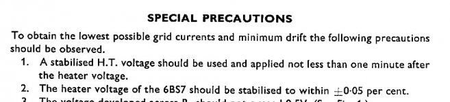
Van de Weijer's advice corresponds exactly to the precautions given by the UK firm Brimar, in an application of their 6BS7 for electrometer applications (ie when lowest grid current is the main objective). In this case, preheating - for one minute is mandatory.
Attachments
Of course, the reality is that many commercial products crash-start the HT onto cold cathodes, in the name of reduced cost.
In the case of consumer-equipment, this is of no consequence at all to the manufacturer. Even if the valves were degraded by grid emission, the customer can pay for replacements. This kind of business practice was universal - and still is.
Further, products like television sets and table radios, and mid-fi amplifiers will not be notably worse for it.
Grid emission is only a problem if one has a proper hi-fi set up that might be spoiled by the extra noise and distortion caused by it.
For this reason, any suggestion that some piece of equipment worked for 150 years without needing new tubes is not evidence that grid emission does not occur.
No doubt also, that some manufacturer's cathodes will be more resistant to disintegration of the cathode surface than others. But since we will never really know, I think it pays to be conservative.
As for DIYers, it all depends on your objectives. I get the impression that many folks build with valves as a pleasant-looking alternative. These folks are not going to be disturbed by a bit of noise or distortion. But if you are building because you want the best possible sound, and the smallest degradation over time, grid emission may be a concern to you.
I'm aware of 'common wisdom' that gas ions might be prevented from striking the cathode surface by a local 'cloud' of thermionic electrons, but is there any substance to it? The ions would be massive and have reasonable energy.....
I always build with separate power switches for filament and B+. Of course on my 833C amp it's absolutely necessary to preheat the filament before slamming the plates with 2300VDC, but I built my 26 preamp with two switches, too. Perhaps it's overkill for tube protection but it also helps when troubleshooting the circuit and if I want to run in some old NOS 26s for a few days with filaments only (reduction of trace gases) it makes it a lot easier to do.
I'm aware of 'common wisdom' that gas ions might be prevented from striking the cathode surface by a local 'cloud' of thermionic electrons, but is there any substance to it? The ions would be massive and have reasonable energy.....
The gas ion would be positively charged and strongly attract a (negatively charged) electron. Once the electron reaches the ion, it converts it into a neutral atom, or molecule, which is no longer attracted to 'bombard' the cathode.
- Status
- Not open for further replies.
- Home
- Amplifiers
- Tubes / Valves
- Getter heater & B+ sequencing ?