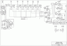
I have now completed my schematics for the preamp PCB but as I have used ExpressPCB and ExpressSCH the files that these programs save as are not compatible with any other PCB manufacturer but ExpressPCB and I do not want them making my PCB.
I have tried a few other more professional PCB CAD programs but I can't understand anything in these programs and desperately need help creating PCB gerber files. I can send over parts list and schematic to anyone willing to help me. The board can be 350mm wide and 300mm deep. It needs all the connections in the back of course and if anyone sees any problems with the schematics, don't hesitate to report back here on the forum for me and others to see and make suggestions for a fix if you know one.
My inspiration are these two pictures, I am a neat-freak and the more "pro" this board ends up looking, the happier I will be 🙂
http://www.sales.highendpalace.com/471200.jpg
http://www.highendpalace.com/633000.jpg
I don't expect this to be free work, and I will gladly donate $ to the person who's design I choose to have manufactured (if someone actually makes one that is good enough that is)
Best regards,
/Daniel
Attachments
Daniel,
I think you need to realize this is a BIG layout project. I have an MSEE and have spent the last 25+ years of my career doing PCB design and layout, and "donating $" is an understatement. If I were to do this for $, it would be BIG $$$$$$.
1. You have specific dimensions.
2. You have somewhat specific placements (what's "at the back"?).
3. There are part symbols in the schematic that are unknown to most EE's.
4. There are no reference designators. Where are the footprints/package descriptions?
4. You want it to look "professional" - what's that?
I think if you're going to do something like this, or even ask someone else to do it, you need to learn a LOT more about electronic design, schematics, layout, and what is and isn't reasonable for even a professional.
Bill
Agree with Bill,
you need all data sheets for all devices.
exact part numbers, including package reference.
Surface mount, through hole, or both.
Number of layers of finished PCB.
Schematic redrawn to match PCB design system used.
A rough guide would be approx 2/3 weeks of quite intensive work, as part libaraies would have to be created, everything checked, everything checked again, then the mechanicals checked, in my case that would be via IDF into Solidworks.
I am interested in doing a pre-amp design but with work load etc I only get to spend a few hours a week on my audio hobby, and on a job like this it would take longer than I think youd be willing to wait.
- Status
- Not open for further replies.
