Hey George,
I was cruising about looking for information on 26 and 27 volt heater tubes and lo and behold came across your "first page" when I searched for 26E6WG. It looked like an interesting tube and I was curious about the PP amp that you made.
If you don't mind sharing I would be interested in what you did. The data sheet that I came across had no curves in it and the "typical characteristics" design was SE only. I was thinking stereo PP with 12AT7 drivers and transformer input splitters.
I found these tubes in a box full of military surplus tubes. I was working on a tube amp for the car where microphonics are a big issue. The 26E6WG looked interesting since it has two short pentodes internally connected in parallel. This makes for a stiff structure reducing microphonics. I later found some ruggedized 6L6 types (5932) using the same construction. I have the same data sheet that you describe, but I assumed that it was similar to the 6CW5 and that may be a valid assumption. The key point to both tubes is that the screen voltage must be lower than the plate voltage.
I did build a breadboarded P-P amp using the 26E6WG. I did it in my usual style of just hooking stuff up and tweaking it until it works. It has been over 7 years since I built the breadboard, so some of the details are fuzzy. I never did build a tube car stereo amp. I can't find my notes from back then either. They are probably in a box in the warehouse.
I probably used a 12AT7 for the driver since I have a zillion mil spec triple mica 6201's that are not microphonic. I have been using them in lots of projects. I don't remember the details of the input stage but most of my designs are either LTP, or direct coupled split load (like the Simple P-P). I know that every P-P amp I built back then used the same OPT since I had just bought about 100 of them. It is the 6600 ohm guitar amp OPT that I still use in most of my experiments today. For it to have worked here I would have been running it at 3300 ohms (8 ohm load on the 16 ohm tap). I was using a hacked 12 volt to 120 volt power inverter for a power supply and these usually make about 240 to 260 VDC. So likely the B+ voltage was in that range. Screen voltage was likely derived using a mosfet follower with either a pot or a zener on the gate. I usually start out with a pot so I can turn knobs to find the best operating point. I didn't have good bench supplies back then like I do now.
I still have about a dozen of the tubes (NIB), maybe more. I doubt that I will ever use them, so if you care to experiment I can send you some for the cost of postage.
BTW George, did you ever try them with heaters in series? Considering running series heaters with a pair of 12AT7 or 12AX7A.
I've heard of auto tube amps before, but given George's reputation I'd really like to have seen this one. I can picture his Mopar car show entry now as the only one with a dedicated hood scoop for the stereo! 😀
-Larry
-Larry
BTW George, did you ever try them with heaters in series?
No, I wired the tubes in parallel and connected them to a 26 volt power supply. I had been working on a project at work that needed a power supply. I designed a boost converter that runs from a car battery and produces 28 volts (adjustable to 26) at 5 amps.
given George's reputation I'd really like to have seen this one. I can picture his Mopar car show entry now as the only one with a dedicated hood scoop for the stereo!
I never completed a vacuum tube car amplifier, but I did perform several experiments that resulted in vacuum tube audio in my car. It would however not have been allowed in a Mopar show since all of my experiments involved a Ford Mustang!
I owned a 1999 Mustang convertible for about 8 years. It came with a Mach 460 sound system that was extremely loud but not particularly good sounding. I wanted to improve it via an infusion of vacuum tubes. I removed the amp since it had died due to water damage. I tried connecting several of my tube amps in place of the SS unit, placing them in the trunk, and powering them by simply plugging them into a 700 watt power inverter. Despite the fact that several people said that it wouldn't work, most amps functioned fine running on the near square wave inverter output. I even had my 845SE DHT amp running in the car for about a week until one of the Chinese 845's failed due to the rough ride.
At the time the roads in our neighborhood were in poor shape and microphonics were the biggest issue. Maybe some of the old timers can remember the spring reverb units that GM installed in some 63 to 65 Pontiac Grand Prix's. I had a 65 Grand Prix and you had to cover your ears when you hit the railroad tracks. Some tube amps were almost as bad. Even output tubes were audible, especially EL34's. I experimented with making a less microphonic amp using tubes like the 26E6WG and tripple mica 5751's and 6201's. I got the breadboard working but it never hit the road. I got lazy and just fixed the SS amp. I came to the conclusion that in a convertible on a busy road the tube amps sound was wasted.
One thought I had was to use a SS bridge rectifier on the line voltage (I am using input transformers) to get about 170V DC after filtering. I could tap the heaters off the DC supply using an appropriate sized light bulb as the dropping resistor to drop the 50V or so needed to get the right heater values. The screen supply I am not sure of. I don't want to get too complicated but maybe some sort of Zener or regulator tube could be used to derive the screen supply from the plate supply. Of course a simple resistor could be used also.
Data sheet indicates 220V max plate voltage and example design is at 200V. If available plate voltage is say 160V could plate current be increased as long as plate diss. is not exceeded (no max plate current is listed)? How do you think it would feel about a little grid current? Thinking maybe AB2.
I don't imagine that you could bust the plate voltage by 35% (300V) safely even on a rugged military tube like this. Doubler would be convenient and I don't think there is a one and a half'er. 🙂
I don't imagine that you could bust the plate voltage by 35% (300V) safely even on a rugged military tube like this. Doubler would be convenient and I don't think there is a one and a half'er. 🙂
I don't imagine that you could bust the plate voltage by 35% (300V) safely even on a rugged military tube like this.
You never know until you try. It is entirely possible that the tubes were never tested beyond the voltage needed in the original application. Someone in this forum has pointed me to a commercial amplifier that claims to run EL84's at 700 volts! I found this hard to believe since that is over TWICE the rated maximum. I haven't been to 700 volts yet but I have been to 450 volts without issue. The key is a regulated and low screen voltage. I haven't tested the 26E6WG recently but I would bet that going past 200 volts isn't going to cause the tube to explode.
It looks like these tubes were intended for SE use where the dissipation is constant. That involves a rather constant cathode current. P-P in class AB will involve a wide range of cathode currents but the cathode in these little guys looks reasonable.
If you decide to venture into unknown teritory, set up your experiments with meters on everything. Watch the plate and screen current. First set the bias to cut the tube off hard. Crank the voltages to or beyond your intended operating point. The tube should remain in cutoff. Increase of negative grid voltage may be needed, but if you can't cut the tube off, you WILL have runaway. If this passes, decrease the negative bias until the desired plate idle current is reached. Leave it there for a while. Some readjustment may be required especially on tubes like these that have been sleeping for 55 years. You should be able to find a stable operating point with no tendency to runaway.
I realized that my bench is empty since the red board has been moved into the living room for some rock concert level testing, so I connected a 26E56WG to a pair of adjustable power supplies and cranked. 300 volts on the plate with 150 on the screen is not a problem. I set the tube at 50 mA which is 15 watts on the plates and there was no glow. The current was stable from the get go. Pushing the current to 75 mA brought the expected redness. The first signs of glow will be on the inside of the plates where they face each other. Returning to the grid voltage that made 50 mA yeilded 50 mA. The tube passes static testing at 300 volts. That doesn't mean it will work with 600 volts of plate swing.
Now if I can find my old SSE board.....
Now if I can find my old SSE board.....
You know me....400 volts didn't blow anything either even at 50 mA. The blue glow starts at 350!
I don't imagine that you could bust the plate voltage by 35% (300V) safely even on a rugged military tube like this. Doubler would be convenient and I don't think there is a one and a half'er. 🙂
VTs are a good deal more forgiving than solid state devices. You also have to take into consideration what applications they had in mind when making the specs. 6BQ6s have a Pd= 12W spec, yet I run 'em at Pd= 17.5W with no problem at all. Of course, audio PP final use doesn't involve putting out max power for hours at a time, as they do running as horizontal deflection finals.
Busting the spec for Vpp(max)= 135Vdc gives nicer loadlines for the 50C5. Another type specifically designed for low voltage operation directly off the AC mains (power xfmr-less designs).
You also have to take into consideration what applications they had in mind when making the specs.
It is an audio output tube for aircraft use and is specified for SE pentode class A, 6 watts output with a 2.6K load and a 200 volt supply.
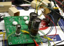
OK, I have been looking for an excuse to wire an octal socket into a Simple P-P, so I did it. I put in a pair of 26E6WG's and cranked them up. THe board was unchanged from EL84 use including 270 ohm cathode resistors for each channel. I used OPT's that are known to work well at 6.6K and 3.3K and are currently running in my red board at 125 WPC so they are not a limitation. I have a seperate power supply on the screen and the plate.
I set the dials for 300 volts plate and 150 volts screen and hit the switch. No smoke no fried parts just 18 watts at 3% distortion with a 6.6K load. Switching to 3.3K resulted in less power and more distortion. The cathode voltage was 14 volts which means 286 volts and 55 mA on the tubes. No glow no excitement, so.....
I cranked the plate up to 400 volts and left the screen at 150 volts. Power went up to 22 watts, again the 3.3K load did not work. The cathode voltage was just over 15 volts so the tube was eating 385 volts and 55 mA. no glow at full power, pale glow when drive is removed.
One more knob twist, this time a little nudge of the screen voltage, up to 170 volts. Power was 28 watts and the tube wasn't glowing at full power.
SO, don't sweat the plate voltage. I would experiment with bias VS screen voltage to find the most efficient operating point. I don't know where the screen voltage limit is, but I wouldn't push it too far with elevated plate voltage.
Attachments
Wow! Thanks George. Tough little buggers it seems. I am saving this information in the project folder for that amp. I was a little bit surprised that the higher plate load worked best. When the time comes I will probably try a doubler for about 300V and cathode bias to start. Am tempted to play with fixed bias but will start with baby steps. 🙂
Am tempted to play with fixed bias but will start with baby steps.
I have the amp wired for fixed bias now. I am currently smoke testing some $1 6EZ5's at and beyond the red zone. I'll get back to the 26E6's.
Fixed bias with the 26E6WG:
I dialed up 400 volts on the power supply which is 402 measured at the plate of the tube. I set the screen supply at 185, 186 measured at the tube. I set the bias for 50 mA per tube which is -22 volts on the grid. This is probably a little harder than you want to run these, but I just gotta crank em.
Distortion at 1 watt.........0.26%
Distortion at 10 watts......0.75%
Power at 5% ...............35 watts.
No glow at full power or at no power. Plate dissipation is 20 watts per tube againat a spec of 12.5 watts. There might be more in these tubes, but I am already way over plate voltage, screen voltage, and plate dissipation specs, so I think it's time to light up some 6BQ6's.
Why do I like sweep tubes? I removed the 26E6WG's, plugged in some 6BQ6's and turned the knobs. At 500 volts plate and 200 volts screen I was getting 75 watts at 5% in the same amp! I bought over 100 of these things for less than $1 each!!!!! What's not to like?
OH, if anyone is interested 12BQ6's and 25BQ6's are still on the dollar menu at ESRC in both GT and GA versions. The GA version takes far more abuse before melting.
OH, if anyone is interested 12BQ6's and 25BQ6's are still on the dollar menu at ESRC in both GT and GA versions. The GA version takes far more abuse before melting.
Why do I like sweep tubes? I removed the 26E6WG's, plugged in some 6BQ6's and turned the knobs. At 500 volts plate and 200 volts screen I was getting 75 watts at 5% in the same amp! I bought over 100 of these things for less than $1 each!!!!! What's not to like?
OH, if anyone is interested 12BQ6's and 25BQ6's are still on the dollar menu at ESRC in both GT and GA versions. The GA version takes far more abuse before melting.
George,
I'm interested. Can you tell me more about the 75W amp, or point me in the right direction? I've got a 750V power transformer with 12.6V secondary just waiting to be used.
Scott
Last edited:
After cranking on some 6BQ6GA's that I got for 76 cents each one developed the gassy blue glow followed by the red glow of death. I swapped it out and retested. Plate voltage 500 volts screen 175 volts tube current 50 mA grid voltage -28 volts.
Distortion at 1 watt.........0.24%
Distortion at 10 watts......0.785%
Distortion at 50 watts ......2.62%
Power at 5% ...............74 watts.
No glow at full power or at no power. Plate dissipation is 25 watts per tube againat a spec of 11 watts. Same plate structure as found in other GE 17.5 watt tubes. GA version only. The GT version has small plates.
- Status
- Not open for further replies.
- Home
- Amplifiers
- Tubes / Valves
- George RE: 26E6WG