Forgive me while I learn these full bridge amps.
This amp powers on, makes rail voltage but has clip light on.
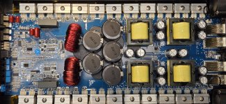
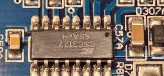
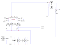
Output doesn't seem to be switching. I believe if I lift Diodes 10/11 that will force the MIC8280 (U7) to send pulses? The driver ICs are CSC3127's? Can't find much of anything on them. They then seem to feed 2 pair of 1797/4672 buffers.
What's the best plan of approach here?
Outputs don't seem to be shorted.
One 1 set of outputs I have G(55v) D(124v) S(55v)
Other set of outputs I have G(0V) D(55v) S(0v)
Same on both sides of the amp.
This amp powers on, makes rail voltage but has clip light on.
Output doesn't seem to be switching. I believe if I lift Diodes 10/11 that will force the MIC8280 (U7) to send pulses? The driver ICs are CSC3127's? Can't find much of anything on them. They then seem to feed 2 pair of 1797/4672 buffers.
What's the best plan of approach here?
Outputs don't seem to be shorted.
One 1 set of outputs I have G(55v) D(124v) S(55v)
Other set of outputs I have G(0V) D(55v) S(0v)
Same on both sides of the amp.
Attachments
Hopefully someone will come in with first-hand knowledge but until then...
Is the 3127 equal to the 20957 like the CSC3120 is the same as the 2092?
Which pins of the 8280 are 5v? Which are 0 ohms to ground?
Are D10/11 connected between the 8280 and the CSD pins of the ICs?
Is the 3127 equal to the 20957 like the CSC3120 is the same as the 2092?
Which pins of the 8280 are 5v? Which are 0 ohms to ground?
Are D10/11 connected between the 8280 and the CSD pins of the ICs?
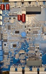
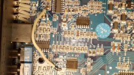
Here is a little trick that will work for most of this style of amps. You can start this amp without the high rail voltage and still get audio out of the amp. Note when doing this please make sure that you signal and load connected to the amp. First, you have to remove the 2 drive ICs for the power supply FETs—then remove R56 which goes to Pin 14 of the MCU. Now above the MCU, you find 5 solder pads the first solder pad will have 5v on it, that pad also goes to Pin 1 on the MCU. Now take a 4K7 resistor, solder one end to that pad, and then solder the other end to C23( which goes to pin 14 of MCU).
Now the amp is in a service mode which makes it safer to work on. After you have done this and before powering up check the bridge rectifiers on both sides and make sure they read ok..
Power up the amp with the signal and load connected and then check pin 1 of the output drive ic you should get 10v.
Then check pin 2 and you should 9v. Now with pin 2 if you get 3v the amp will clip and 0v on pin 2 will put the amp into protect.
Check pin 3 and make sure you are getting a PWM signal to it.
GThe check pin 11 which should give you Low side Output and pin 14 which is high side output.
If you are not getting PWM on pin3 you will need to check pin 7 and pin 12 and 13 of IC uc3124(that is what it looks like from your pic). Those pins are sends put the PWM to your drive ICs.
Also, another common thing is the RCA GND pin sometimes breaks so check that as well.
For now, this is a good start. There is more that you can check but I don't want to confuse you with all the information.

Is it accurate that the technique in #3 only works for amplifiers that include the 12v B+ voltage in their rail voltage? Something like the attached diagram.
It's good information but I want to clarify. Low-voltage has been used in other amplifiers but it has to be supplied from various sources.
It's good information but I want to clarify. Low-voltage has been used in other amplifiers but it has to be supplied from various sources.
Attachments
Yes. These amps have buck converters that they use to make up the various voltages for preamp and drive circuits
Why aren't people testing defaced FETs to find what they are?
https://www.diyaudio.com/community/threads/testing-of-defaced-fets.424170/post-7934862
https://www.diyaudio.com/community/threads/testing-of-defaced-fets.424170/post-7934862
Last edited:
Today I had one of these 8k and 5k amps come in for repairs. I managed to see what power supply fets they are using. IRFB7437. I am sure they are using this in the 5k as well. I could make out the number on the output sections.
With these generic amps, I have previously used these in the power supply CDS18502 or IRF1404 with no comebacks. The only thing I changed was the gate resistor from 4R7 to 10R. The fets had no heating problems. In fact I did once do a bench test with a dummy load with the CSD and IRF fets installed and found that the amp power supply section ran much cooler. I had installed an amp in my daily car and had no problems with it.
For the output section, I have used the following :
1) With Rail caps rated at 160v I use IRFB4321 or IRFB4115. I have also noticed that many new amps coming out of China and starting to use the IRFB4115 be it a 4ch or mono amp.
2) With rail caps rated at 200v I use IRFB4127 or IRFB 4227.
I know people are going to question the protection circuit of these amps but having compared this amp to the Sound Digital and looking at the Sound Digital circuit diagram the protection circuit is the same. The only difference I have found between Sound Digital and the clone amps is the voltage divider circuit that they use for the MCU. The clone values are different from SD and on the drive circuit there are a few resistors that are different from SD amps. Also, on the output the clone amps have 4148 didoes on the output fets and the SD does not.
So far from the amount of clone amps I have repaired, I have never had any comebacks within 6 months of repair. Most of these amps go into our South African version of a MINIBUS Taxi and these guys play these hard all day long. The only time I had one comeback was due to a client not having enough battery power for the amp.
I strongly believe that looking at the success rate I have had with using the FETS that SD uses on their amps the same components I use seem to work well.
Sorry guys. Just getting back to this one. The outputs are labelled P2. The amp is brand new. Was only bench powered to test (by the shop owner) before shipping to a customer, he says it went straight into clip.
@laluns I'll get on all this stuff here shortly and go from there. Appreciate your input.
@Perry Babin I'll check all that out soon as I get into it sir, thanks.
Quick question...
If my rail voltage is at 124v... shouldn't my half way point be 62v? and not 55v? Would this be the cause of the clip light? What controls that "half way" point?
I'll update soon! Thanks everyone.
Some of these amps (I don't know if this one uses it) had a problem with the voltage divider in the 'float' circuit. That can cause a bias point that's not at 1/2 of the regulated voltage.
I'm thinking that could be at least part of my problem. Well, I'm bought to get to learning a whole lot about this amp design! So, here we go!
Thank you everyone in advance!
Thank you everyone in advance!
@laluns I have done as you have said. I use a QuantAsylum as my signal generator. You say to "Power up the amp with the signal and load connected" I assume you want me to be playing a 50hz tone into the amp when I power it up? Powering it up, I'm connecting to main power, ground and remote?
Attachments
Ok..
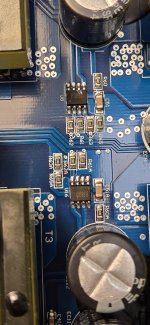
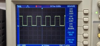
Pin 1 of the CSC3127 has 10.24v, Pin 2 has 5.75v, Pin 3 square drive, on both ICs.
The power light cycles slowly, the clip light (original problem) is staying solid, and protect light blinking fast.
Pins 11(15.17v) and 14 (15.36v) of both CSC3127s have voltage but no switching
Pin 1 of the CSC3127 has 10.24v, Pin 2 has 5.75v, Pin 3 square drive, on both ICs.
The power light cycles slowly, the clip light (original problem) is staying solid, and protect light blinking fast.
Pins 11(15.17v) and 14 (15.36v) of both CSC3127s have voltage but no switching
Attachments
Last edited:
Something else I noticed. The above readings were with my scope using the mains ground as reference. If I move the ground to the RCA shield, I only have about 6volts at start that slowly lowers. I switched to my multimeter. Black probe on RCA shield, Red on pin 11. As soon as I remove the remote power (pin 11 was around 5v), the voltage goes from positive to negative like -3.5v and slowly climbs up toward zero. Not sure if it has something to do with the fact I'm driving a signal into it or not.
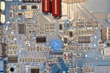
Also noticed, the output filter inductors are mounted up high and definitely loose. But the solder connections seem ok
Also noticed, the output filter inductors are mounted up high and definitely loose. But the solder connections seem ok
Last edited:
You have the MCu connected wrong. You must put a 4k7 resistor on that first pad and the other end onto pin 14 of the MCU. From your PIC on post #12 you can connect the other end of that resistor to C34, which looks like it is connected to PIN 14 of the MCU. With all the clone amps I get C34 is labeled C23. I will post a pic of how it should be done later today when I work on a few of these amps I have for repairs. The GND for the scope should be on one GND terminal of the amp. and not on RCA GND.
You can use a 50hz signal
You can use a 50hz signal
Good morning Laluns.
Ok, moved the jumper. Thought that was a bit strange but it does lead back to pin 14 through C34. Connected it to C34 pin 14 side.
New readings using main ground.
Pin 1: +10.3v
Pin 2: +4.0v
Pin 3: switching
Pin 11: +15.4v
Pin 14: +15.7v
Now the power and protect lights only come on when it tries to start up cycling and the clip light is blinking fast.
Attachments

Last edited:
First, can you confirm that you removed the power supply drive ICs, which are "U8" and "U16"? Also, confirm that the link you installed measures 4k7, as I see you have used an SMD resistor. The reason I ask you to confirm these 2 things is because all you are doing with this 4k7 resistor link is fooling the MCU to think that full rail voltage is present in the amp. On pin 14, you should get around 800 to about 950mv.
If the above turns out ok, then you will need to check all the drive transistors. I would suggest testing them to do so with the transistors out of the board. If the transistors test out fine, then check all the Gate resistors as well as the 4148 diodes and the 15v zener diodes. For the Zener and 4148 diodes, I would also suggest testing them out of the board. If these tests are all ok, then check the underside of the board for any broken or burnt tracks. Also, check all diodes and resitors on the drive circuits
If you don't find anything above, you will need to find which side of the outputs is faulty. I always do this when I have this type of fault.
Remove one drive IC. It does not matter which one you remove. Now, switch on the am,p and you should get power and clip light on. Check pin 2 of the drive IC that is remaining on the board. You should get between 9V and 10V, and also check the high and low side output pins 11 and 14. Should you bet getting HIgh and Low side outputs, then you know that this side of the amp is good. Now, switch off the amp, remove the good side drive IC, install the other side drive IC, and repeat the same check.
Please try these steps and let me know.
- Home
- General Interest
- Car Audio
- Generic 8k full bridge