Hello everybody,
I am new here and not sure if I post this in the correct thread. I'm currently working on an amplitude modulated microphone. It is a very old idea published originally in the 60th.
For it to work I need to generate a carrier frequency that is fed into a bifilar wound transformer to generate a higher voltage version of the same carrier with 0 deg phase and 180 deg phase.
I got it all working using a 10 kHz carrier signal. However so far I generate the signal using a function generator. Obviously not very convenient.
What I need is a reliable circuit that creates a 10 kHz (or similar frequency) sine wave with good frequency stability. I experimented a bit with quartz stabilized Colpitts oscillators but the results are not encouraging at all. I never got anything that looks close to a sine wave. All waveforms I got were quite distorted.
I could use a DAC and a filter but I thought there must be an easier way.
Any suggestions?
Thanks
Try making a 10kHz MP3 file (or burn a CDR) using Audacity. It takes seconds to create the file.
This is a little old now but essentially still applies. Some of the plug ins are not needed now as they are built in.
Installing and using Audacity. A get you started guide.
Edit... I think I misread your question. You are looking for a permanent circuit solution, not just something to test it with.
How stable does the frequency need to be?
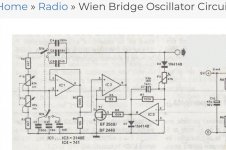
Would a simple opamp based sine generator be adequate? I'm thinking of a Wein Bridge type, preferably using one of those tiny 'grain of wheat' bulbs for amplitude stabilisation although it can be done with diodes but is less good. Very low distortion when done properly and very simple to build.
https://www.ti.com/lit/an/sloa060/sloa060.pdf
Hi Mooly,
thanks for the suggestions. Generating an audio file is easy to do either with audacity or with Python which I prefer. I have done it many times and it works great. I was looking for a hardware solution.
The idea of using a light bulb as non linear element always turned me off. Mostly because light bulbs are increasingly a thing of the past. But maybe the AGC version mentioned in the application document is a way forward. I will look into that one a bit deeper.
I have not done my homework for the frequency stability requirement yet. I use a digital demodulation that is based on least squares fitting a sine wave to sections of the digital data stream. Deviations in frequency are automatically put into deviations in amplitude by this scheme.
Kind regards
Stefan
Bulbs are old fashioned but they also are perfect for the job. They don't even pass enough current to glow in such a circuit and so last pretty much indefinitely.
Many thanks,
I just went through the basic calculations and will give it a try a bit later today. So far without a bulb as I don't have one. Maybe I can salvage one from an old flashlight.
I just went through the basic calculations and will give it a try a bit later today. So far without a bulb as I don't have one. Maybe I can salvage one from an old flashlight.
A flashlight bulb will be far to hefty and low resistance. You need something that draws a few tens of milliamps at most (for full brightness).
Random examples:
https://cpc.farnell.com/sli-ebt/7219-004/wire-ended-3mm-12v-1-9-lumens/dp/SC00339?st=bulbs
https://cpc.farnell.com/unbranded/f015d/lamp-sub-min-w-e-12v-blue-pk2/dp/AR70320?st=bulbs
Random examples:
https://cpc.farnell.com/sli-ebt/7219-004/wire-ended-3mm-12v-1-9-lumens/dp/SC00339?st=bulbs
https://cpc.farnell.com/unbranded/f015d/lamp-sub-min-w-e-12v-blue-pk2/dp/AR70320?st=bulbs
Attachments

You can also use a Weinbridge oscillator. If you Google around, the design equations to select f will be given. In the attached circuit, the JFET essentially replaces the bulb (I used this years ago - it works well!) so you get low power consumption.
Attachments
I am aware of mikes using FM principles. Not AM.
0 and 180 waves is just an inverter.
I'm not sure why an "AM mike" needs great frequency stability?
0 and 180 waves is just an inverter.
I'm not sure why an "AM mike" needs great frequency stability?
Quick update,
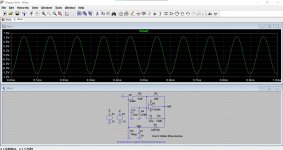
for now I decided to try a digital solution first using a AD9833. A small test PCB with the chip and a 25MHz oscillator arrived in the mail yesterday and the results are not bad. Frequency stability is god as expected and overall performance is OK. A super simplistic test with the AD9833 going into a cheap 1000pF cap and from there into the oscilloscope shows a bit more than 40 dB between the fundamental and the 7th harmonic. Other harmonics are smaller. So THD is worse for 10 kHz than the values mentioned in the data sheet but I'm not worried about that. A small filter will bring it to levels I can live with. The SNR is a bit better than 60 dB as promised in the data sheet. The signal amplitude is 540 mV PP something that can easily be filtered and amplified to my desired levels.
All in all not bad for a very simple test.

Hi Lampie519,
thanks for the interesting schematics. The idea is similar a closer description of what I do would be found in a paper from Baxandall http://www.jp137.com/lts/Baxandall.RF.mic.pdf .
The lower part of figure 2 shows the idea for the analog section. I am only interested in very low frequencies so I work with a lower carrier frequency. The other difference is that I don't use an analog demodulator. Instead I sample the amplitude modulated signal and do the demodulation digitally.
I am aware of mikes using FM principles. Not AM.
...found in a paper from Baxandall...
Thanks. I should have suspected that such a "different drummer" technique would be by Baxandall.
- Home
- Source & Line
- Analog Line Level
- Generate frequency stable sine wave