gedlee said:
In other words - getting the on axis and off axis responses to hold together (1 dB in this context is impossible) is far more important than 1 dB in absolute response.
Thats something that most people will not have a problem with. (..of course with your design I'd say it was critical, but then most people don't use waveguides or very directive large diameter drivers.)
And 1 db can be a big deal from about 1-3 kHz, but that's what most people refer to as "voicing" for their crossover when fiddling with component values to get the freq. response they want for the axis they have designed for.
Do you actually do an integration of the area above and below? If so, to what time extent and what allowable tolerance do you use?gedlee said:
...
Below is a fairly typical impulse response - note reflection starting after the initial response. Note that the waveforem MUST be above zero as much as it is below zero. The woofer is raised by 10 compared to the waveguide. You need to be looking at nice clean impulses like this before you can begin to do anything. You need to be able to find the direct sound and the reflections. If you can't tell where one starts and the other ends then you have too small of a space.
I get back later when I have more time.
My ECM8000 eventually reaches a 6dB rise at about 12KHz. without compensating for this somehow (whether on or off axis), you will end up padding down the speaker too much or mistune a tweeter parallel notch (wrong target frequency).
My post wasn't meant to allude to ignoring power (off-axis) response in speakers. In fact it is just as much, if not more important than on-axis. My post was about how to remove errors from measurement so regardless of what axis you measure - your microphone isn't giving a misleading boost to the response.
Cheers,
David.
When measuring drivers, I like to do using half space radiation with the driver mounted on a large baffle 2.4Mx2.4M (limited by room size). This will allow better understanding on what to expect when mounted on speaker baffle.
Same here.gedlee said:
Thats another reason why I just leave the reflections, it makes them obvious. There is nothing worse than finding that the crummy data you have was because you didn't get rid of all the refections, but didn't realize it. Even a small reflection - barely visible in the impulse response, can have major effects. Thats because the impulse is linear and FR's are log. This is why some people square and take the log of the impulse (Energy-time) because it highlights the reflections and things that make differences in the FR in dB.
I also did some measurements in a small anechoic room, and it gave almost the same results as in a normal office space of same size.
Dave Bullet said:nullspace / Patrick,
If you want to design a speaker with a +/- 1dB response through most of the range, I personally believe microphone calibration is essential in one form or another.
My mic is packed up and is to be shipped to KimG on Monday...
Thanks everyone for the contributions thus far.
Regards,
John
ScottG said:
Thats something that most people will not have a problem with. (..of course with your design I'd say it was critical, but then most people don't use waveguides or very directive large diameter drivers.)
And 1 db can be a big deal from about 1-3 kHz, but that's what most people refer to as "voicing" for their crossover when fiddling with component values to get the freq. response they want for the axis they have designed for.
I really think the concept of controlling a loudspeaker response to 1 dB is unrealistic. I have never seen such a thing except at a single point with DSP equalization, but of course this drove the off axis responses to +-6 dB.
Its important to keep a perspective on the goal, and +- 1 dB ain't it. +- 2dB fro 200 - 10 kHz and -22.5° to + 22.5° is the best that I have ever seen. +- 1 dB within this range is simply out of the range of possibility with todays technology.
soongsc said:
Do you actually do an integration of the area above and below? If so, to what time extent and what allowable tolerance do you use?
I have actually done this, but in my measurements its always acceptable. But I have actually seen people post impulse responses that obviuosly did not satisfy this criteria and expect me to accept tham as valid. Dah...
Dave Bullet said:My ECM8000 eventually reaches a 6dB rise at about 12KHz. without compensating for this somehow (whether on or off axis), you will end up padding down the speaker too much or mistune a tweeter parallel notch (wrong target frequency).
My post wasn't meant to allude to ignoring power (off-axis) response in speakers. In fact it is just as much, if not more important than on-axis. My post was about how to remove errors from measurement so regardless of what axis you measure - your microphone isn't giving a misleading boost to the response.
Cheers,
David.
No contest here - I did not expect the Berhinger to be this far off. I actually use an Earthworks calibrated mic for most of my measurements, but once I was caught having to use the Berhinger and it seemed to work fine. If its off by 6 dB at 12 kHz then this is a problem, but I think that we were talking about 1 dB stuff, and I just can't accept 1 dB as a reasonable expectation.
I would like to see some valid calibration curves for this mic. I think that data is always better than memory or "experience".
I do have two questions:gedlee said:
...
I have actually done this, but in my measurements its always acceptable. But I have actually seen people post impulse responses that obviuosly did not satisfy this criteria and expect me to accept tham as valid. Dah...
...
1. Did you actually integrate the areas for the whole data duration or just for a specific time frame? With impulse data that you questioned, you have actually conducted the same calculation? Normally the area criteria might be true over an infinit time, this does not seem reasonable in real world test data.
2. Drivers do have some off-set caused by linearity of spiders and actual design implementation. This normally is not modeled in all the design equations. Wouldn't the resulting impulse not show above 0 area equaling below 0 area?
Taken these two conditions, it seems reasonable to assume that a certain range of error should be acceptable, and the allowable error now becomes subjective.😀
Member
Joined 2003
I would like to see some valid calibration curves for this mic.
Earl,
Here is my ECM 8000...calibrated by Kim G.
For a $40 mic, it's darned good from 20-20k. There is some unit-unit variation so this one isn't necessarily the same as other examples.
Paul
An externally hosted image should be here but it was not working when we last tested it.
gedlee said:
I really think the concept of controlling a loudspeaker response to 1 dB is unrealistic. I have never seen such a thing except at a single point with DSP equalization, but of course this drove the off axis responses to +-6 dB.
Its important to keep a perspective on the goal, and +- 1 dB ain't it. +- 2dB fro 200 - 10 kHz and -22.5° to + 22.5° is the best that I have ever seen. +- 1 dB within this range is simply out of the range of possibility with todays technology.
I'd agree, but it can be advantageous to have that +/-1db (modestly averaged) for more limited passbands like that 1-3kHz for the listener's axis. This of course isn't even suggesting that it should be at the same level as the average, after all there are more than a few studies that suggest otherwise (..I think BBC compensation curve 2 or 3 relies on a "plateau" here).
I think that +/- 1db isn't out of the range of possibility (though I doubt if I've seen it). If you "expand" horizontal off-axis (say +/- 30 degrees or more) as a requirement then it can be achieved with a full radial configuration, though usually at the expense of vertical dispersion.
Here is Dan's latest semi-radial (..which considering his near non-existent DIY-loudspeaker experience just 2 years ago is nothing short of astonishing):
http://www.htguide.com/forum/showthread.php4?t=28906
Even considering that the little tweeter beams at the top of its passband, not to shabby eh?😉
nullspace/John..
At this point in time I'd have a hard time recommending anything other than SoundEasy.
In part because of the new cepstral deconvolution, which should allow for better measurements in a limited space.
But I'd also suggest it because its a pretty comprehensive all-in-one package and because it has broad support.
In the past I've used Loudspeaker Lab (early version).. but I've allocated the funds to purchase SoundEasy v15 for when its released.
IMO (for at least the software side of things), it not so much about learning what type of method is best.. but rather just learning to use the software as recommended. For that your best bet is contacting other users of Arta (if thats the software you have decided on).
For the "mechanical side" of things I used a semi-pit/large baffle for the base measurements that would latter be "massaged" by the modeling.
This was nothing more than hanging my mic via a large length of string from the ceiling that could be adjusted for distance (..with 2 loop pins in the ceiling - one at the center of the room for the mic and the other at the rooms edge/wall for the adjustment portion of the string).
The driver's "stand" was just some fence grating glued over over a large cardboard tube (sonotube like) stuffed with pillow fiber and draped with a heavy blanket. (..its likely that the sonotube could have easily been a bucket or something else.) The height of the sonotube was cut to about 1 1/2 feet (and then of course there was the distance added by the driver itself). (..it was an 8 foot high room - so almost 2 meters to a reflection point.) Pillows and blankets were arrayed around the sonotube pillar/stand.
The baffle was ultra simple: a 2 piece affair, both cardboard.
The center (driver) baffle (18" by 18" square) was made for each type of driver under test. The material is cheap, easily cut with an exacto knife (for the particular driver's hole), has very little thickness to induce resonances, and with painters tape is easily connected and disconnected both to the driver and the secondary baffle.
The larger (secondary) baffle was approximately 13 foot square with the 18" by 18" square cutout in the center. It was suspended at whatever height was needed using the same method as the mic with string attachments at each corner of the square. 2 Parallel sides of this baffle used two square dowels extending down the length of the baffle attached to the "outside" edge to extend limited support (all taped together).
It was crude, but effective and *very* removable.😉
Cepstral decovolution in the current V14 is just a beginning. Lots of manual involvement is necessary. Idealy there should be a method of filtering room reflections. Let's hope that that something more advanced evolves.
Other than that, SE seems to be the most bang for the buck considering all the features and the integration of the design workflow.
Other than that, SE seems to be the most bang for the buck considering all the features and the integration of the design workflow.
soongsc said:
I do have two questions:
1. Did you actually integrate the areas for the whole data duration or just for a specific time frame? With impulse data that you questioned, you have actually conducted the same calculation? Normally the area criteria might be true over an infinit time, this does not seem reasonable in real world test data.
2. Drivers do have some off-set caused by linearity of spiders and actual design implementation. This normally is not modeled in all the design equations. Wouldn't the resulting impulse not show above 0 area equaling below 0 area?
Taken these two conditions, it seems reasonable to assume that a certain range of error should be acceptable, and the allowable error now becomes subjective.😀
Its the sound radiation that cannot have a DC content. What the source does is irrelavent. Over a very short time period the integration will not go to zero, but as the time gets longer it has to. Basically if the impulse does not average to zero then it is wrong.
Paul W said:
Earl,
Here is my ECM 8000...calibrated by Kim G.
For a $40 mic, it's darned good from 20-20k. There is some unit-unit variation so this one isn't necessarily the same as other examples.
Paul
Thanks - this is no where near the 6 dB that was claimed!! More like 2 dB. Having designed a lot of mics before I could not see any reason that the error should be 6 dB. What you showed is exactly what I would have expected. Its amazing how real data can dispel a lot of false claims.
ScottG said:
I'd agree, but it can be advantageous to have that +/-1db (modestly averaged) for more limited passbands like that 1-3kHz for the listener's axis. This of course isn't even suggesting that it should be at the same level as the average, after all there are more than a few studies that suggest otherwise (..I think BBC compensation curve 2 or 3 relies on a "plateau" here).
I think that +/- 1db isn't out of the range of possibility (though I doubt if I've seen it). If you "expand" horizontal off-axis (say +/- 30 degrees or more) as a requirement then it can be achieved with a full radial configuration, though usually at the expense of vertical dispersion.
Here is Dan's latest semi-radial (..which considering his near non-existent DIY-loudspeaker experience just 2 years ago is nothing short of astonishing):
I don't follow your first paragraph. Your just not giving up on this 1 dB stuff are you? I still think that its a rather absurd hope that I've never seen in practice and I really doubt that I ever will.
Your example shows typical meaningless single point measurements. What do things look like at other points? And its very important to have a narrow directivity not a wide one.
soongsc said:Cepstral decovolution in the current V14 is just a beginning. Lots of manual involvement is necessary. Idealy there should be a method of filtering room reflections. Let's hope that that something more advanced evolves.
I wouldn't waste a lot of time on cepstral techniques. They have ben around for decades and never seemed to find any useful applications.
gedlee said:
Its the sound radiation that cannot have a DC content. What the source does is irrelavent. Over a very short time period the integration will not go to zero, but as the time gets longer it has to. Basically if the impulse does not average to zero then it is wrong.
...
Yes, I hear you. Once I asked an MS in controls why he assumed K (contant gain) for the sensor for the control system in his thesis; the response was "Because that's what the books say." Not very realistic. I suppose he found a more idealistic place to work.
...
I wouldn't waste a lot of time on cepstral techniques. They have ben around for decades and never seemed to find any useful applications.
Various ideas were floating around. I'm sure various techniques work to different extents, we shall see in the future. I'm sure where there is a will there is a way.😉
Here is my cal file for the ECM8000:
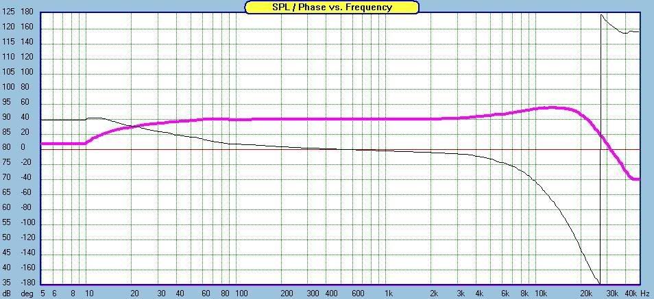
Probably about 4 dB hot at 13k Hz. There seems to be at least two distinct versions. I have the later one. The early ones have an obviously different response, but I don't have any screenshots of those.
Probably about 4 dB hot at 13k Hz. There seems to be at least two distinct versions. I have the later one. The early ones have an obviously different response, but I don't have any screenshots of those.
gedlee said:
I don't follow your first paragraph. Your just not giving up on this 1 dB stuff are you? I still think that its a rather absurd hope that I've never seen in practice and I really doubt that I ever will.
Your example shows typical meaningless single point measurements. What do things look like at other points? And its very important to have a narrow directivity not a wide one.
I wouldn't waste a lot of time on cepstral techniques. They have ben around for decades and never seemed to find any useful applications.
..its not so much an absurd hope, as rather an over generalized description - as is +/- 2 db in general.
The link wasn't an "example" per se, just something interesting. If you had bothered to scroll down you might have seen some off-axis measurements.😉 ..and of course I'd strongly argue the opposite - that is *very* important to have WIDE directivity, not narrow. 🙂
As for Cepstral decovolution, I wouldn't dismiss it off-hand.. in this application users would have a better idea of functionality - and yes, it could be several versions before something truly useful evolves (..if in fact thats the case).
ScottG said:nullspace/John..
At this point in time I'd have a hard time recommending anything other than SoundEasy...
Thanks for your thoughts Scott. I'm pretty much set on ARTA right now for measurements.
Interesting setup for measuring; I'll have to see what I come up with.
Regards,
John
ScottG said:The link wasn't an "example" per se, just something interesting. If you had bothered to scroll down you might have seen some off-axis measurements.😉 ..and of course I'd strongly argue the opposite - that is *very* important to have WIDE directivity, not narrow. 🙂
As for Cepstral decovolution, I wouldn't dismiss it off-hand.. in this application users would have a better idea of functionality - and yes, it could be several versions before something truly useful evolves (..if in fact thats the case).
Well you'd have to make the argument for wide directivity because I don't think that the rational is sound. The argument for narrow directivity exciting fewer room boundaries and early reflections is pretty compelling.
I didn't "dimiss it off-hand" I've done a lot of cepstral work. It just doesn't do anything for the loudspeaker problem. It works well for noise control and that sort of thing for finding periodic sources and the number of them. Thats where it shines, and what it was orginally developed for. But for the loudspeaker problem where I know the number of sources, where they are located and I can control the input signal, cepstum doesn't tell us nearly as much as the impulse response and nothing that the impulse response can't tell us. The impulse response has all of the information that can be gleaned from a single measurement.
gedlee said:
Well you'd have to make the argument for wide directivity because I don't think that the rational is sound.
I didn't "dimiss it off-hand"
Such an argument is not on topic.. but I'm sure there will be other threads.😉
In this specific application (in context) it very much appeared to be such a dismissal. The whole point of it (at least from the description) is to remove noise - i.e. the room (or rather its reflections). The thing is, I can't find any actual user information on its success or lack thereof when doing searches.. so who knows? Its possible that JohnK might have more information on this topic. Bottom line - it *may* have potential.
BTW, what did you think of Dan's project? (..of course I knew you would have a problem with the lack of directivity, but that wasn't the point of the original discussion.) Also note that you could use the radial approach in a hyper-cardioid to limit directivity.. but again, off-topic.
nullspace said:
Thanks for your thoughts Scott. I'm pretty much set on ARTA right now for measurements.
Interesting setup for measuring; I'll have to see what I come up with.
Regards,
John
Your welcome! Play around, spend some time - you'll get there. 😉
While this is not intended to sway your decision on Arta, this is IMO an important statement I pulled from dlr on the HTGuide site:
"Being repetitious here, the multi-way stereo digital filter is in-disposable to me at this point. It's great to swap different designs in minutes for comparison purposes, no hardware required, other than the up-front cost of a 6-channel amp, that is."
Its only a couple of sentences, but within it underlies a wealth of information on saving your time and money with this hobby.
- Status
- Not open for further replies.
- Home
- Loudspeakers
- Multi-Way
- Geddes et al on Measuring Loudspeakers