Of course a chip amp is very versatile. This version inverts
the input polarities and accomplishes the same thing.
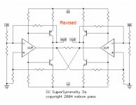
Notice the nested loops, and the resistor in the center which
is the SS connection.
www.passlabs.com/np/GC-SS-3a.pdf

the input polarities and accomplishes the same thing.
Notice the nested loops, and the resistor in the center which
is the SS connection.
www.passlabs.com/np/GC-SS-3a.pdf
Well, National >does< call them 'smart transistors', and in
this context it helps to think of them that way. Using
the voltage rails to drive the output transistors still doesn't
look 'right' at first until I think of the chips as a transistor
with emitter and collector--with differential bases!
Then the pieces of the puzzle fall into place and I can start
to see the picture. I was going to object to the idea that
the chips themselves were plenty powerful, but with the
nested feedback that concept jumps ahead and looks much
more interesting!
This might be worth that headache after all.
Arigato, sensei; this slow student may be learning to think, however slowly.
Next question: does that 'transistor' actually behave something
like a discrete transistor? There may be surprises lurking within.
The "collector" and "emitter" might be very symmetrical in
behavior, unlike a discrete transistor (we hope so!), but are
they really linear?
I suspect this is a case where a CCS would be inappropriate.
This is all the time I have to puzzle over it; have to go fix supper!
Damon Hill said:does that 'transistor' actually behave something
like a discrete transistor? There may be surprises lurking within.
The "collector" and "emitter" might be very symmetrical in
behavior, unlike a discrete transistor (we hope so!), but are
they really linear?
With the local feedback around the chip it looks a lot like some
sort of idealized transistor, but you surmise correctly about
the potential for surprises.
The
 is in the details.
Go.to.bed:
The 3a hardly looks SuperSymmetric.
I would try X-shape feedbacks from the outputs to the + nodes of the chips.
Euro2004 adds my lack of 😴.
The 3a hardly looks SuperSymmetric.
I would try X-shape feedbacks from the outputs to the + nodes of the chips.
Euro2004 adds my lack of 😴.
Chipamps here?
I never thought Mr. Pass would ever use an op-amp.😕
Well... times they are a'changin' I guess...🙄
I never thought Mr. Pass would ever use an op-amp.😕
Well... times they are a'changin' I guess...🙄
Xed already
Hi,
in this case the SuSy is implemented already by the single
resistor between the opamps outputs.
Uli

jh6you said:
The 3a hardly looks SuperSymmetric.
Hi,
in this case the SuSy is implemented already by the single
resistor between the opamps outputs.
Uli

don`t know
Hi,
I do not know yet, have to think it over
The magic resistor between the OPAs outputs feeds error
current into the output of the other OPA thus causing this amp
to feed reverse current into this resistor. This error current is
drawn from the supply. This in turn leads to creating this error
current out of phase at the output -> SuSy.
Your pic is indeed food for thought
Uli
Re: Chipamps here?
The circuits are for your consideration, partly in response to
a comment that you can't do anything interesting with a chip
amp. I use op amps all the time, but I usually prefer to "roll
my own" 😎
carlosfm said:I never thought Mr. Pass would ever use an op-amp
The circuits are for your consideration, partly in response to
a comment that you can't do anything interesting with a chip
amp. I use op amps all the time, but I usually prefer to "roll
my own" 😎
- Status
- Not open for further replies.
- Home
- Amplifiers
- Pass Labs
- GC SuperSymmetry pt III