staring at a functioning board with capictors facing me, the LEDS should look like|/| on both sides.
Make sure your other jumper points are done correctly.
Here is a pic with almost all the jumper points installed (assumes SemiSouth, no degeneration.) IGNORE the LED symbol orientation on this one, the production boards switched that.
R11,12 were not jumpered, but bypassed to do even without the input JFETs in this configuration. (I did not stick with that, performed much better with them in there)
Last edited:
Good news LED's lit bad news still nothing across r14 Shouldn't I be getting a bias voltage there now?
If your using Mosfets than you likely need two LEDs. At least one of them blue IMO.
We want around 4.2 v or higher for the mosfets to conduct.
Even with R100's I remember the biasing was a bit sudden, not gradual. So I would take it slowly.
We want around 4.2 v or higher for the mosfets to conduct.
Even with R100's I remember the biasing was a bit sudden, not gradual. So I would take it slowly.
End of year inventory check -
5 pair of boards left. Some power supply boards also if needed.
all daughter cards are available.
5 pair of boards left. Some power supply boards also if needed.
all daughter cards are available.
F6 build - How to set the bias
Hi,
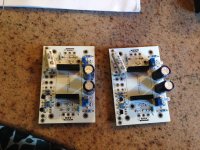
Trying to complete a long pending project during this Christmas vacation. I finished stuffing the Tea-bag's F6 boards with all the components and also jumpered the un-utilized LED and output degeneration resistor and preset slots.
I have the required Semisouths as well.
Now I need to test the boards. I do not have a variac but have a light bulb setup. To begin with, do I set the bias pots to zero resistance, and if yes, to which side? Also do I set the offset pots to centre?
Please help.
Attached is the picture. Please let me know.
Cheers.
Hi,
Trying to complete a long pending project during this Christmas vacation. I finished stuffing the Tea-bag's F6 boards with all the components and also jumpered the un-utilized LED and output degeneration resistor and preset slots.
I have the required Semisouths as well.
Now I need to test the boards. I do not have a variac but have a light bulb setup. To begin with, do I set the bias pots to zero resistance, and if yes, to which side? Also do I set the offset pots to centre?
Please help.
Attached is the picture. Please let me know.
Cheers.
Attachments
I would install the transformers, and try to get units LEDs to light up with without the FETs installed. Should get voltage over the toshiba JFETs.
If that works, then install FETS, but get the Pots at the lower Ohm reading first, by measuring underside of unit.
If that works, then install FETS, but get the Pots at the lower Ohm reading first, by measuring underside of unit.
I would install the transformers, and try to get units LEDs to light up with without the FETs installed. Should get voltage over the toshiba JFETs.
If that works, then install FETS, but get the Pots at the lower Ohm reading first, by measuring underside of unit.
Thanks. The daughter boards with Jensens are ready. Will plug and check.
Cheers.
If that works, then install FETS, but get the Pots at the lower Ohm reading first, by measuring underside of unit.
Should I measure pots to zero towards the side indicated as CW on the circuit ? Also where do I measure bias? On the set of parallel resistors in the PS?
Thanks in advance.
Cheers
I measure the pots on the underside of PCB.
Yes, measure the bias from the power supply resistors.
Yes, measure the bias from the power supply resistors.
Pot is maxing out for bias on one channel
Hi,
Managed to get both the channels up and running. Adjusted the bias and offset on one channel to 1.5 amps measured on the resistors of the power supply on one rail. While the other channel biased as well, the bias preset is maxing out at 1.2 amps. Do I need to reduce the 10K resistor value (R4) in series with the bias LED, or should I change the LED?
Need some help. My understanding of the circuitry is sketchy.
I am using Semisouth PowerJFets in the output.
Cheers.
Hi Anilva,
What is the voltage across the Semisouths from gate to source?
Are you using Blue LED?
What is the voltage across the Semisouths from gate to source?
Are you using Blue LED?
Fellow diyers,
Just to shared my thoughts wrt resistor feeding LEDs and 5 k trimmers,
LEDs in general prefer to be well forward biased for the Vf to be well establish. For a typical blue LED, 3v forward voltage correspond to about 10 - 20mA forward current (some variation depending on make). In reality one also needs to consider 5 k pot in parallel with LED. Assuming 3v across LED, there will 2mA flowing through 10k resistor with 0.6 mA is going through pot (3v/5000) leaving 1.4mA for LED. 1.4mA is far from ideal for running any LED maybe that is the reason why there large variation in experience.
I'm using 1.2k instead with 2 blue LEDs. Reason I'm using 2 blue with in my setup is to produce about 6.2v ref voltage which gives able voltage to explore SS or IRF or any other lat fets. Pots takes 1.2mA leaving about 12 ~ 13mA for LED. Question for all, why isn't there a cap for smoothing of the Vref generated by LEDs?
Just sharing
Sent from my C6903 using Tapatalk 2
Hi There,
If anyone was looking for these boards. I ordered and have 10 sets in stock.
Let me know if your interested.
Tea
If anyone was looking for these boards. I ordered and have 10 sets in stock.
Let me know if your interested.
Tea
...And all good here. Tea Bag came through with some lovely boards and Jensen was pretty swift with some transfo's. I'm fairly sure I have everything else I might need on hand, so off we go when I get some diy time.
Question though - the Jfets at the front end are just working as a buffer, so, other than noise, whats the consequence of substituting in differing jfets? Come to think of it, the answer to that is drive current to the transformers, so allow me to rephrase.
Is the reduction of drive current significant enough to impact performance? I have enough J175 and j310's on hand to find a franken-match between some...
Last edited:
not answering your question, but the original article or work on this discussed use without a buffer. I tried it, but without success. I was getting some woofer wobbling if you will.
I will, I wish, I wouldn't want a woofer wobble. Ahem. Apologies to Dr Seuss...
Before I start the psu boards are excellent too, so thank you. Destined for an F3 build, as I might also have a couple of smps on hand to use for this guy.
I think i have a few lsk jfets here anyway, so I dont need to find sub parts but I'm always curious 🙂
Thanks again Tea Bag!
Before I start the psu boards are excellent too, so thank you. Destined for an F3 build, as I might also have a couple of smps on hand to use for this guy.
I think i have a few lsk jfets here anyway, so I dont need to find sub parts but I'm always curious 🙂
Thanks again Tea Bag!
...A question if I may?
There was a great document done by one of the members around matching Jfets and degeneration. They went into quite the graphical analysis to match curves between '74's and '170's. Does anyone know what that document name is and where I'd find it?
There was a great document done by one of the members around matching Jfets and degeneration. They went into quite the graphical analysis to match curves between '74's and '170's. Does anyone know what that document name is and where I'd find it?
...A question if I may?
There was a great document done by one of the members around matching Jfets and degeneration. They went into quite the graphical analysis to match curves between '74's and '170's. Does anyone know what that document name is and where I'd find it?
I think jackinnj wrote something to that affect, but this goes back into the F5 days I beleive. You could PM him about it. Between him and EVUL they recommended I think 10R on N 2SK and 15R on 2SJ if you will. Jack has a fairly nice curve tracer, and other test stuff, so was able to perform such tests.
- Status
- Not open for further replies.
- Home
- Group Buys
- GB for F6 Convertible Clone boards