Does anywone have a datasheet or something for this amp? I think somewone has put the wrong transistors in it.
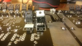
Those two are regulators for +-15V rails, probably for an inputstage. I suggest looking for shorts in the output-transistors.
Still the one on the right looks like the ones in mds amp and its the only one that looks like that in this amp.
Then use a multimeter and measure if it still puts out 15V? If it is bad and has been replaced before, the problem that made it fail probably still is there. Or it needs better cooling.
Yes but the problem is that it blows the fuses instantly so i cant put Any voltage in to the amp to mesaure.
I hope somewone have the same amp and could help me out and look at theirs what supposed to be there.
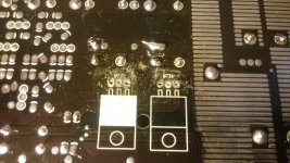
The 7815 would have center leg connected to ground.So test from the pads to see which
one that has ground connection in the center. If that is what they actually using .
7915 first leg goes to ground
one that has ground connection in the center. If that is what they actually using .
7915 first leg goes to ground
The U marking is used for integrated circuits, like opamps and regulators. The 7815 proves +15V and the 7915 the -15V. I can give you a tip: if you don't know what a part is, just google it and look at the datasheet.
7815 and 7915 regulators are cheap and any electronics store should have them. I would just replace them and see if they fail again. If they do, something else is wrong.
The 7915 will need an insulator or be of the fully plastic type, otherwise you short the IN to to the ground (datasheet from google). That probably is why there was a plastic 7915 in there. Some thermal grease might be in order, they could have failed from heat.
You should check the board around the regulators for open circuits, it looks like it has seen some heat.
http://www.mouser.com/Semiconductor...age-Regulators/_/N-5cg9g?Keyword=7915&FS=True shows all the different 7915 regulators Mouser has, as an example.
Last edited:
Great tip! Then next time i might not look so stupid🙂
Im going to buy those new and see what happens.
Im going to buy those new and see what happens.
Mesarued on the pads and there are ground on all of them so there is something more thats wrong.
Im going to take out all of the transistors and rectifiers and see if some of them are boken.
Im going to take out all of the transistors and rectifiers and see if some of them are boken.
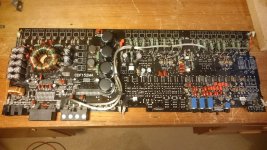
You don't have to do all of them. If it is an normal dual rail amplifier, you can look for a short from the positive supply to the ground and from the negative supply to the ground. Only if they both measure shorted you need to check all of them.
If you take them all out (including the driver transistors), make sure to check if the PCB still is shorted. It shouldn't be.
All this assuming it is a normal dual-rail amplifier. If there are big capacitors, you'll want to check those for shorts. If it has a switched mode supply there is a reasonable chance the problem is in there, capacitors in SMPS have a limited life.
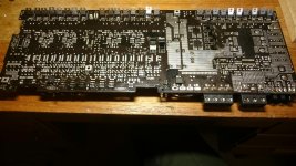
Do you have a pic of the other side of the board?
If you take them all out (including the driver transistors), make sure to check if the PCB still is shorted. It shouldn't be.
All this assuming it is a normal dual-rail amplifier. If there are big capacitors, you'll want to check those for shorts. If it has a switched mode supply there is a reasonable chance the problem is in there, capacitors in SMPS have a limited life.
Do you have a pic of the other side of the board?
I have mesaured between ground and all legs of the transistors and there is about 1 ohm and climbing on all the legs, exatly the same on the next 8.
On the rectifiers there are 0.625 to 0.637ohm on all legs.
And on the 10 transistors i think are the driver transistors i have 0.213 on the outer leg on all of them and the 2 others legs it just beeps constantly.
The big capacitors there are 2 of them thats just beeps constantly and the 2 others start at 0.1ohm and climbs instantly, do i have to take them out to mesaure them properly?
- Status
- Not open for further replies.
- Home
- General Interest
- Car Audio
- Gas silver c2