I'm curious about the air gap width vs the winding width (thickness of all wire layers summed). You can get more B if the gap is narrower, but more windings (hence L) if gap is wider. I think I remember Dan mention that it's better to have more force coming from B?
Anyway, if I have a large gap does it make sense to wrap shorter windings but with more layers (thicker) which redudes the effective gap-air distance and subjectively increases the resulting force. The goal being increased efficiency.
Anyway, if I have a large gap does it make sense to wrap shorter windings but with more layers (thicker) which redudes the effective gap-air distance and subjectively increases the resulting force. The goal being increased efficiency.
Attachments
I think it's true that more B from narrower gap is better. If you wind too much, the Qes could go higher as a result of increased resistance of the coil. So, the lower the resistance/inductance is, the higher the current trough the coil will be. Some drivers are sold in 4 and 8 ohm coil versions and it often seems to be that the 4 ohm has a lower Qes.
I don't really know too much about electricity etc but "someone" once told me the above 🙄
I don't really know too much about electricity etc but "someone" once told me the above 🙄
You can get more windings by making the gap longer.
Making the gap wider is a bad idea.
Filling the gap with windings does not make it appear thinner.
The gap needs to be small enough to allow the poles to saturate.
Once its thin enough theres no point making it thinner, conversely
if its too wide you need more magnetic force, i.e. a bigger magnet
to create the force required for the gap.
Making the gap longer also requires more magnet to provide
the extra flux needed.
For efficiency you need an optimum gap width and length to
suit the fitted magnet.
Your issue then is excursion capability, how much of the coil is
in the gap, the lower the excursion capability the higher the
efficiency and the lower Qe thus Qts is.
🙂 sreten.
This is an interesting question. As I have understood it, the volume of air in the gap multiplied by B is proportional to the energy stored in the magnet. This is given that the pole pieces can carry the magnetic flux to the gap and there is no stray field.
This gap, we should do our very best to fill up with copper. We would use a thin wire and many windings if we want a high impedance, and vice versa, but the gep should be filler with copper conducting the signal current.
Now, given the above, is it better with few layers of wire? This would make the gap narrower, and given a certain magnet energy, the height of the gap could be made longer. If we use, say 50% of the voice coil's length to be within the gap, and leave the rest as overhang, the Xmax value would increase for the VC with few layers. Also, the surface/volume ratio would increase, so heat dissipation would improve.
Are there any reasons at all to make the voice coil have more than one layer? Mechanical precision?
All wired up and no where to go
Hello Vikash!
You have the correct idea on how things work. Ideally you would like to have many layers of wire in a gap to give a good B factor. The trade of is that many layers will need a small diameter wire and therefore push up the R of the coil. The higher R value will raise the Qes and limit the high frequency limit because of the higher inductance. More wire can also mean more mass and then less efficiency. There are happy mediums. You can have twice the number of turns by choosing wires with 1/2 the circular mills. The only problems is that your R goes through the roof. I think that I remember you playing around with FEM and that is a good place to start fooling around with the possible combinations keeping in mind your final goals of Qts, Qes R and so on. You can also do rough and ready calculations with a wire table and calculating the length that you will end up using. It will prove or disprove an idea very quickly based on diameter, resistance and how much will fit into your gap.
I'm going through the same joy in trying to come up with an optimum voice coil for our Parthenon. The shop may be closed but the mind still works!!!!
MArk
Svante said:This is an interesting question. As I have understood it, the volume of air in the gap multiplied by B is proportional to the energy stored in the magnet.
Are there any reasons at all to make the voice coil have more than one layer? Mechanical precision?
When I was a young man the gap flux density was
given in Gauss and the total flux given in Maxwells.
I've always thought its the total gap CSA that counts,
having a wide gap means you need more magnetic force
to create the flux.
Filling the gap with copper is important as it minimises
the resistance of the coil, so how wide the gap is I
suppose is determined by coil resistance.
I don't know why but multilayer voice coils appear to
have higher power handling than single layer, perhaps
the extra layers help each other not to start coming
apart, when a single layer starts coming apart you
get a hotspot and failure is consequently inevitable.
🙂 sreten.
A bit more background...
I've resurrected my DIY transducer project. One of the main problems was in manufacturing a usable former/voice coil. The two issues before were a) the gap size (1.2mm) was IMO too small for an experimenting project, and b) the former wasn't the right size.
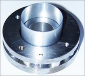
So I've opened the gap by 1mm and had an aluminium former made to fit correctly into the gap (pic in first post). The drop in sensitivity is relatively large even though I've now overcome the VC scraping issue by using a better former.
Now, my mistake was in doing both things simaltaneously (manufacture a former and open the gap at the same time) as it would seem that having a suitable former would have been enough.
So anyway, I have a large gap to work with. This is a given. I think, my bottom line curiousity is based on the observation that flux travels poorly through air and by putting more copper in the gap, the distance is reduced (before the coil actes upon it). So the underlying question was whether in doing it would increase efficiency.
Excursion is a non-issue for this project.
The current winding is with 0.125mm wire and is approximately the same height as the top plate. It measures 7.6 Ohms already with only a single winding. If I change the winding to a third of its height with 3 layers, will it have an effect on efficiency? I also have thicker wire up to 0.265mm to play with. What's the best approach to increasing effeciency?
I've resurrected my DIY transducer project. One of the main problems was in manufacturing a usable former/voice coil. The two issues before were a) the gap size (1.2mm) was IMO too small for an experimenting project, and b) the former wasn't the right size.
So I've opened the gap by 1mm and had an aluminium former made to fit correctly into the gap (pic in first post). The drop in sensitivity is relatively large even though I've now overcome the VC scraping issue by using a better former.
Now, my mistake was in doing both things simaltaneously (manufacture a former and open the gap at the same time) as it would seem that having a suitable former would have been enough.
So anyway, I have a large gap to work with. This is a given. I think, my bottom line curiousity is based on the observation that flux travels poorly through air and by putting more copper in the gap, the distance is reduced (before the coil actes upon it). So the underlying question was whether in doing it would increase efficiency.
Excursion is a non-issue for this project.
Yes I see that the flux must travel between poles to complete the circuit and perhaps irrespective of how much opposing force is in it's path and/or where the flux lines are cut. Though I'm still trying to make clear sense of all these thoughts 🙁Filling the gap with windings does not make it appear thinner.
The current winding is with 0.125mm wire and is approximately the same height as the top plate. It measures 7.6 Ohms already with only a single winding. If I change the winding to a third of its height with 3 layers, will it have an effect on efficiency? I also have thicker wire up to 0.265mm to play with. What's the best approach to increasing effeciency?
Efficiency could be affected by the aluminium former. As the conductor moves through a change in the magnetic field, eddy currents form inside it and it thus dissipates energy (reduces Qms).
Usually no-one should care about the B quoted for a speaker, but rather it's more interesting to know what the BL product is. If you want a stronger force from the magnet motor, then increase the total amount of current travelling within the magnetic field. You can do that by either increasing the amplifier voltage or by using the limited amount of space in air-gap more effectively. The latter method reduces Qes.
If the voice-coil wires were superconductive, then the force would be huge even at low voltage. But, since you have to make do with copper, if you use thin wires a high proportion of space taken up will be for the enamel coating, and if you use thick wires there will be more unused space. Another option is to use extremely thin ribbon wire.
CM
I would think that the spreadsheet I attached in the earlier DIY driver thread should help with most of these questions.
I tried adding a magnet design section using some equations and data from magnet suppliers on the internet, but I was getting gap flux values like 4T for what seemed like typical ceramic magnet configurations - either I am doing something wrong, or gaps are thoroughly saturated. I haven't yet compared to an FEM simulation....
I would suggest playing with FEMM for the magnet system design.
Efficiency could be affected by the aluminium former. As the conductor moves through a change in the magnetic field, eddy currents form inside it and it thus dissipates energy (reduces Qms).
Surely the aluminium former will form a shorted turn in the gap ?
I will have to re-read the basics on this..., but I remember reading that sometimes the aluminium former is rolled with a slit to prevent a shorted turn. I think this is how the eddy currents are reduced. But is this a pre-requisite of alumium formers? It would be a shame as cutting a slit in the former opens up a whole can of VC winding worms.
I will wire up a card former with the same winding spec and see if there is a large difference...
Somthing that is probably nothing (and makes no sense to me, but...):
When I drop the aluminium former into the air gap I notice a very abundant decrease in velocity, a slow-down, when moving through the gap. I just brushed this off as my eyes playing tricks on me, but maybe it's something I should mention.
I think a max of ~2.4T is achieveable with the optimium materials configuration (Permendure). The best I have done modeling with pure iron and high grade Neo's is ~2.1T in a tiny air gap.I was getting gap flux values like 4T for what seemed like typical ceramic magnet configurations - either I am doing something wrong, or gaps are thoroughly saturated.
Vikash said:Somthing that is probably nothing (and makes no sense to me, but...):
When I drop the aluminium former into the air gap I notice a very abundant decrease in velocity, a slow-down, when moving through the gap. I just brushed this off as my eyes playing tricks on me, but maybe it's something I should mention.
That is the shorted turn doing its stuff.
I've only ever heard of a shorted turn being used deliberately
once, in the Celestion SL6's original copper metal dome. Here
is was used to increase damping, i.e. lower Q, but the copper
dome ended up being around 80dB/W !
You could cut some rings from your former, these could be
used as "brakes" placed either end of the voicecoil proper.
Your former appears to much thicker than I've seen on drivers.
You could roll one out of aluminium foil*, keeping it on the
former whilst "wet winding" the voice coil, once the coil is
added it should be able to keep its shape.
(* As long as the surface has poor electrical conductivity
this will not form a shorted turn and a slit is not needed)
🙂 sreten.
The former is 0.5mm thick.
Any idea how hot a VC gets? I have easy access to various plastics (polyethylene, polypropylene, acrylic, u-pvc) which could be feasible for this project if this aluminium former proves defunct.
Going back to some old posts, a shorted turn/faraday ring is purposely implemented to reduce eddy currents, so I don't fully understand if it's a good or bad thing have an aluminium former. Or is it that the ring is usually implemented at the base of the pole which has an important effect?
I read somewhere that 180 degrees C is a not-unusual maximum temp before things start cooking with the VC. Your eyes weren't playing tricks on you: an Al former really does slow down, and it'll probably give a very low Qms if the difference is big enough to be visible. I agree with Sreten: cutting a narrow slit down one side should make a big difference.
CM
CM
The former needs to be split or it won't move properly. Just so things are clear, Qms has no effect on sensitivity in the midband, but really low values (like from a shorted turn) could give you a Qms and Qts that is very low - like 0.05. This would reduce the sensitivity in the bass region. You could have a driver with a 20Hz resonance that has a 100Hz+ F3....
See:
http://www.adireaudio.com/tech_papers/rdo_operation.htm
to calculate the effects of a shorted turn.
I have some speakers with aluminum formers and when I put new surrounds on them, it appeared that the (split) former was about as thick as a soda can - namely about 0.003-0.005 inches (around 0.1mm).
VC's can get as hot as 280C in high power drivers - that is approximately the point where Re is doubled. You won't want to go that high with a Neo motor - the curie temperature for Neo magnets is just over 100C.
Vikash said:The former is 0.5mm thick.
Any idea how hot a VC gets? I have easy access to various plastics (polyethylene, polypropylene, acrylic, u-pvc) which could be feasible for this project if this aluminium former proves defunct.
Going back to some old posts, a shorted turn/faraday ring is purposely implemented to reduce eddy currents, so I don't fully understand if it's a good or bad thing have an aluminium former. Or is it that the ring is usually implemented at the base of the pole which has an important effect?
The thermal power handling in the midrange is determined by
something melting, so your construction will determine maximum
temperature.
A shorted turn in the magnet structure resists change of flux,
lowering distortion. It must be physically fixed in place, the
base of the pole is a good spot. Copper plating the pole
piece also has a similar effect as far as I understand.
IMO a shorted former is a bad idea, unless Q is too high.
Shorted rings at both ends of the voice coil are a good idea.
I'll also note for an aluminium former aluminium wire is a
good idea if you want to avoid thermal expansion issues.
🙂 sreten.
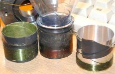
I did some tests, especially now that I have a wider air gap and can fit the old coils in without them scraping. I also found a good test diaphram: a plastic bottle with the top cut off which slots tightly into the former (with a few winds of tape).
The results were inspiring. The alu. former is a definite no-no in comparisson to the the paper formers. I have so much more high freq. information with the paper former; perhaps enough to pull off some kind of full-range driver with this project.
I did try different windings on the alumium former including a two layer thick wire short winding which gave me lots more output, but still uncomparable to a single layer thin wired paper former.
I also was throwing a lot of current into the coil and I could barely feel an temp. increase, though it was only for a minute or so. Max excursion is less than 2mm I would say.
Attachments
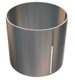
This may be a silly question, but I must ask if the slit needs to go all the way through, or can I leave a bit at both ends of the former so that it will keep its shape while winding the VC. i.e is the effect of the shorted turn prevented if the loop is not in the gap?
Attachments
- Status
- Not open for further replies.
- Home
- Loudspeakers
- Multi-Way
- Gap width vs winding thickness